Supercharge Your Innovation With Domain-Expert AI Agents!

Multi piece turpocharger housing

a turpocharger and housing technology, applied in the direction of engine lubrication, motors, leakage prevention, etc., can solve the problems of premature ignition of the fuel-air mixture in the cold housing, large amount of friction energy released, and risk of sliding bearing damage, etc., to achieve simple and economical manufacturing, light weight

Inactive Publication Date: 2013-05-23
SCHAEFFLER TECH AG & CO KG
View PDF4 Cites 3 Cited by
  • Summary
  • Abstract
  • Description
  • Claims
  • Application Information

AI Technical Summary

Benefits of technology

The present invention provides a lighter turbocharger housing that is simple and economic to manufacture without compromising its functionality. The housing is made up of two parts connected through a joining method, such as welding or glueing, which ensures tightness and prevents leakage of cooling water during operation. The cooling water conduit formed by the connection between the two parts is pre-formed without the need for a complex and expensive casting method. The housing parts can be made through cold-formation of sheet metal or machining methods, resulting in a through-put of cooling water up to four times greater than conventional cast parts while keeping the outer dimensions unchanged.

Problems solved by technology

As a rule, the shaft of the turbocharger is mounted in the turbocharger housing through a sliding bearing, with the consequence that a large amount of friction energy is released in the form of heat exactly inside the bearing receptacle of the turbocharger housing.
An eventual failure of the cooling of the turbocharger housing creates a risk of damage to the sliding bearing and a premature ignition of the fuel-air mixture in the cold housing.
Turbocharger housings made out of cast metal do indeed manifest an excellent thermal conductivity but possess, on the other hand, a heavy weight and give rise to very high manufacturing costs precisely due to the very complex integration of the cooling water conduit which, however, is indispensable.

Method used


Image

  • Multi piece turpocharger housing
  • Multi piece turpocharger housing
  • Multi piece turpocharger housing

Examples


Embodiment Construction

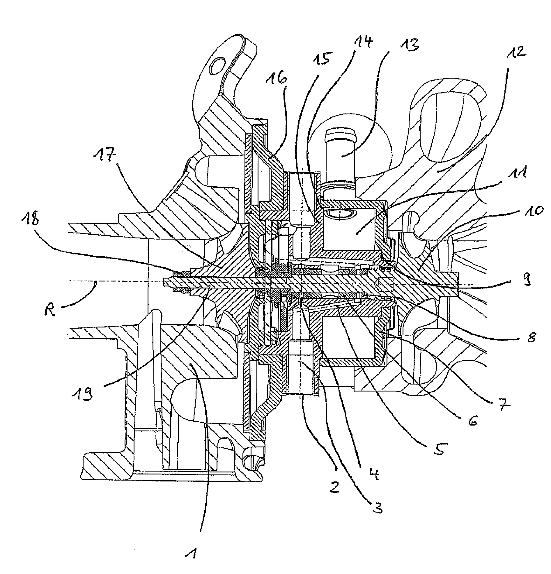
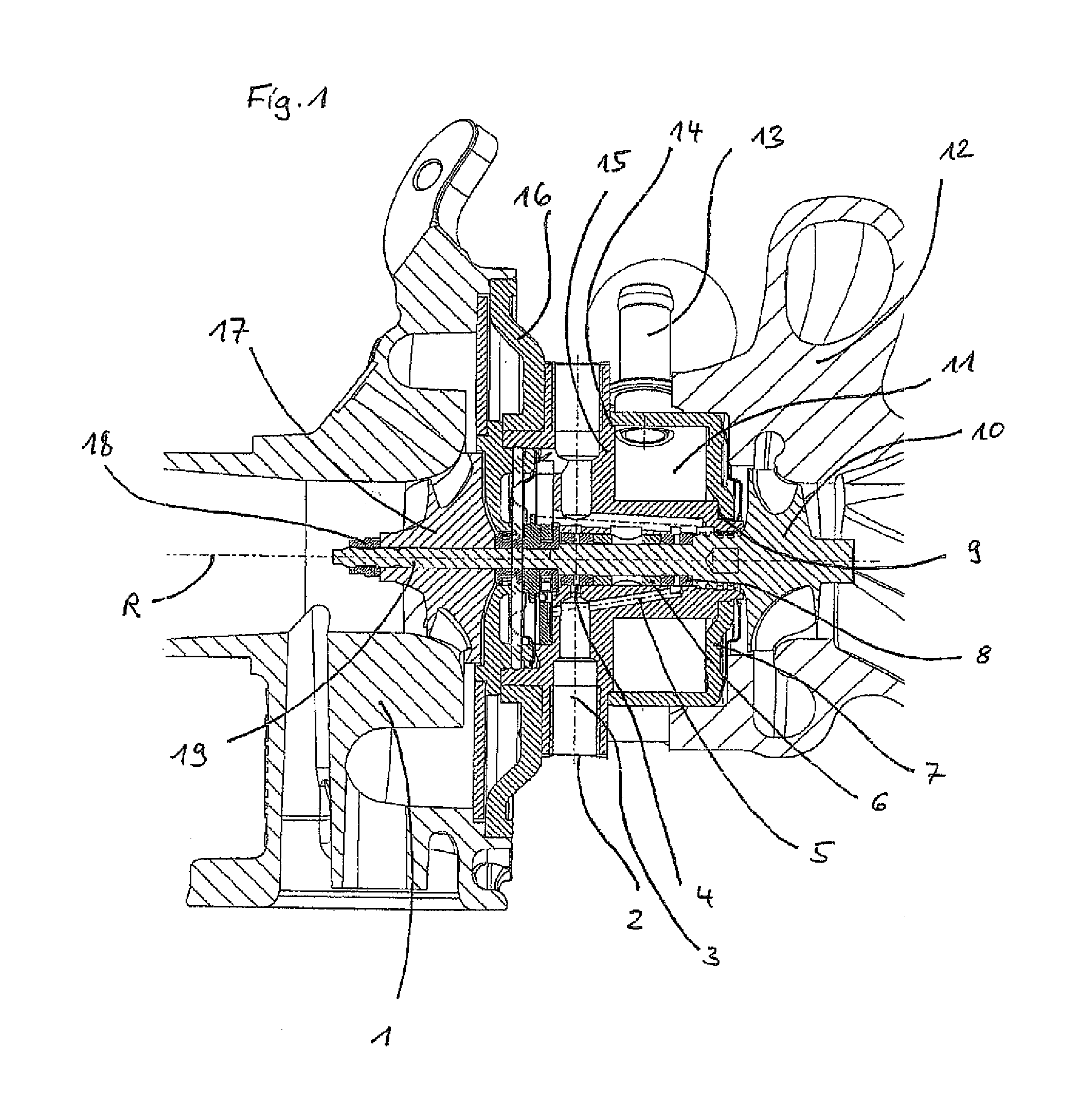
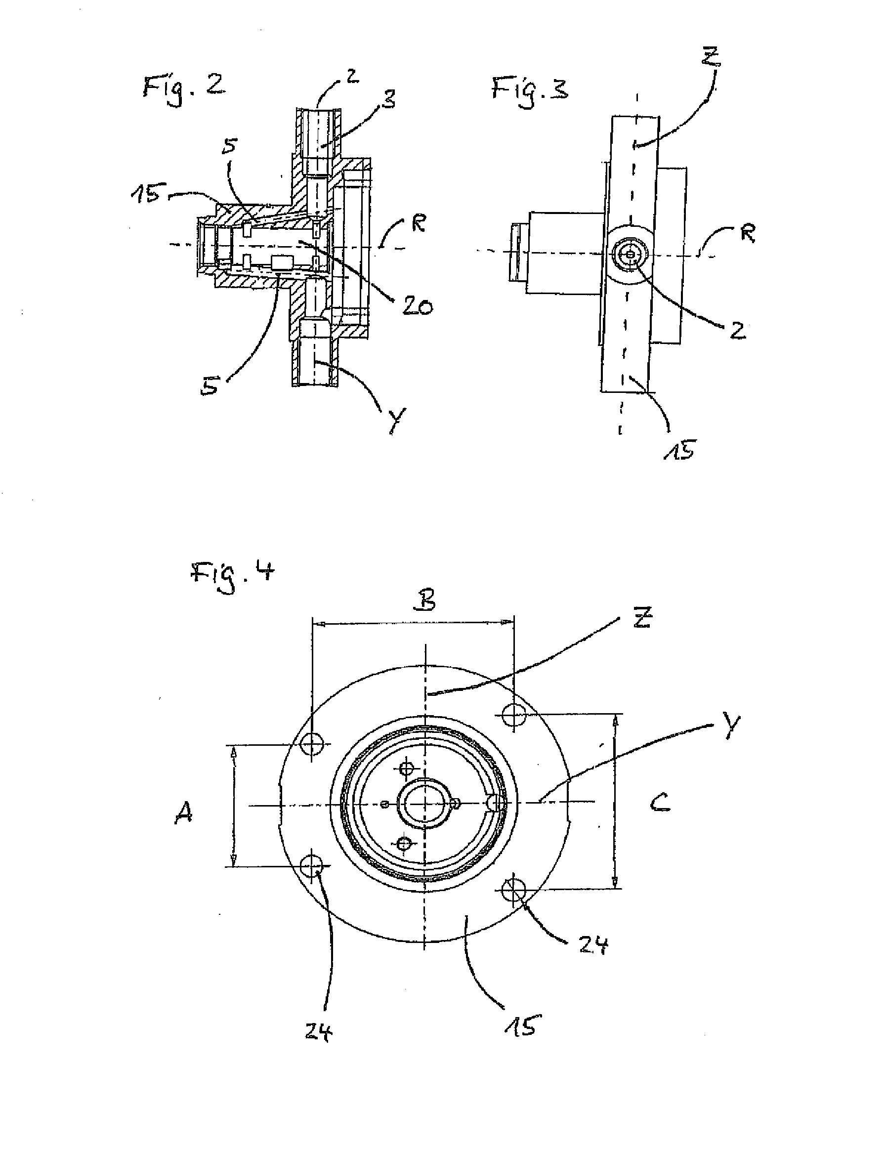
[0032]FIG. 1 shows a sliding bearing mounted turbocharger comprising a three piece turbocharger housing, in a longitudinal section along the axis of rotation R. The first housing part 15 of the turbocharger housing is configured as a machine-finished forged part, in longitudinal section along the axis of rotation R.

[0033]The turbocharger housing comprises the first housing part 15, the second housing part 7 and the third housing part 16. The turbocharger housing is arranged between the cold housing 1 and the hot housing and screwed to both of these housings.

[0034]The shaft 19 connects the turbine 10, which is arranged in the hot housing 12, to the compressor 17 which is fixed on the shaft 19 with help of a fixing element 18, e.g. a nut. The shaft 19 is configured in one piece with turbine 10 so that, due to heat conduction, a basic danger of heat migrating out of the hot housing 12 into the cold housing 1 exists.

[0035]The water conduit 11 comprises a sectional surface of a square or...


PUM


Abstract

A turbocharger casing including a first casing part, wherein an oil line starts at a first opening on an outer side of the first casing part, runs through the first casing part and opens out at a second opening of a substantially hollow-cylindrical bearing receptacle of the first casing part. Such turbocharger casings of the prior art are produced in a complicated manner by a sand casting process and therefore give rise to high production costs. The teaching is to arrive, without functional losses, at a simple-to-produce and cost-effective turbocharger casing by the turbocharger casing having a second casing part attached to the first casing part and by both casing parts together forming a cooling water line provided for cooling the bearing receptacle. It is thus possible to arrive at a lightweight turbocharger casing by conventional machining production methods and joining technique, and this turbocharger casing can be produced cost-effectively.

Description

[0001]The invention concerns a turbocharger housing in which an oil duct starts at a first opening of an outer side of the first housing part, extends right through the first housing part to open at a second opening into a substantially hollow cylindrical bearing receptacle of the first housing part. The invention further concerns a turbocharger comprising such a housing.BACKGROUND[0002]Turbochargers are used for improving the performance of internal combustion engines in which the kinetic energy of the exhaust gas stream is extracted with help of a turbine and is used to press the fuel-air mixture into the internal combustion engine with help of a common shaft of the turbine and of a compressor. In this way, the fixed cubic capacity of the internal combustion engine can be filled with larger quantity of the mixture so that a higher lifting force and thus also a higher engine performance is achieved during combustion.[0003]In passenger vehicles, turbochargers or rather the shaft of ...

Claims


Application Information

Patent Timeline
Patent Type & Authority Applications(United States)
IPC IPC(8): F01D25/24
CPCF01D25/125F01D25/14F01D25/18F01D25/246F02C6/12F01D25/24F05D2220/40F05D2230/238F05D2230/232F05D2230/64F05D2250/42F02C7/06F01D25/145F05D2230/237
Inventor DAUT, KLAUSHASCHKE, RICHARDBAIER, RICHARD
Owner SCHAEFFLER TECH AG & CO KG
Features
  • R&D
  • Intellectual Property
  • Life Sciences
  • Materials
  • Tech Scout
  • Unparalleled Data Quality
  • Higher Quality Content
  • 60% Fewer Hallucinations
Learn More