
Systems and methods for rendering with ray tracing

a technology of ray tracing and system methods, applied in the field of two-dimensional representation rendering, can solve the problems of computational complexity, large computational time requirements of workstations, and inability to test 1024768 (for example) rays for intersection with millions of triangles,

Active Publication Date: 2009-05-21
IMAGINATION TECH LTD
View PDF48 Cites 106 Cited by
  • Summary
  • Abstract
  • Description
  • Claims
  • Application Information

AI Technical Summary

Benefits of technology

[0028]Such systems also may provide that each ray may be tested against the primitives in an order different than an order that the ray would naturally traverse the scene, and the intersection testing resource is further configured for maintaining information concerning a current closest detected intersection.

Problems solved by technology

However, ray tracing is also known to be computationally intensive, and at present, even a state of the art graphics workstation requires a substantial amount of time to render a complicated scene using ray tracing.
As can be readily understood, the computational complexity of testing 1024×768 (for example) rays for intersection with millions of triangles is computationally expensive—and such ray numbers do not even account for all of the additional rays spawned as a result of material interaction with intersecting rays).
It has been understood that tracing rays through a scene can require practically random access to an enormous amount of scene geometry.
Such prediction has been found to be difficult in ray tracing, such that when using a tiered cache computer for ray tracing, the caches can thrash a great deal.
On the other hand, providing enough fast memory to allow random access to all the primitives composing an entire complex scene is quite expensive and beyond the capabilities of most conventional systems.
In the future, it is expected that scene resolution and complexity will continue to increase, and thus even though computers will become more powerful, with more memory, and higher memory bandwidths, the problem described above is expected to continue.
Pharr recognizes that the proposed regular scheduling grid may not perform well if a particular scene has non-uniform complexity, i.e., a higher density of primitives in some portions of the scene.
Such rays can be increasingly difficult to identify as rays are reflected, refracted and / or generated during ray tracing.

Method used


Image

  • Systems and methods for rendering with ray tracing
  • Systems and methods for rendering with ray tracing
  • Systems and methods for rendering with ray tracing

Examples


Embodiment Construction

[0047]The following description is presented to enable a person of ordinary skill in the art to make and use various aspects of the inventions. Descriptions of specific techniques, implementations and applications are provided only as examples. Various modifications to the examples described herein may be apparent to those skilled in the art, and the general principles defined herein may be applied to other examples and applications without departing from the scope of the invention.

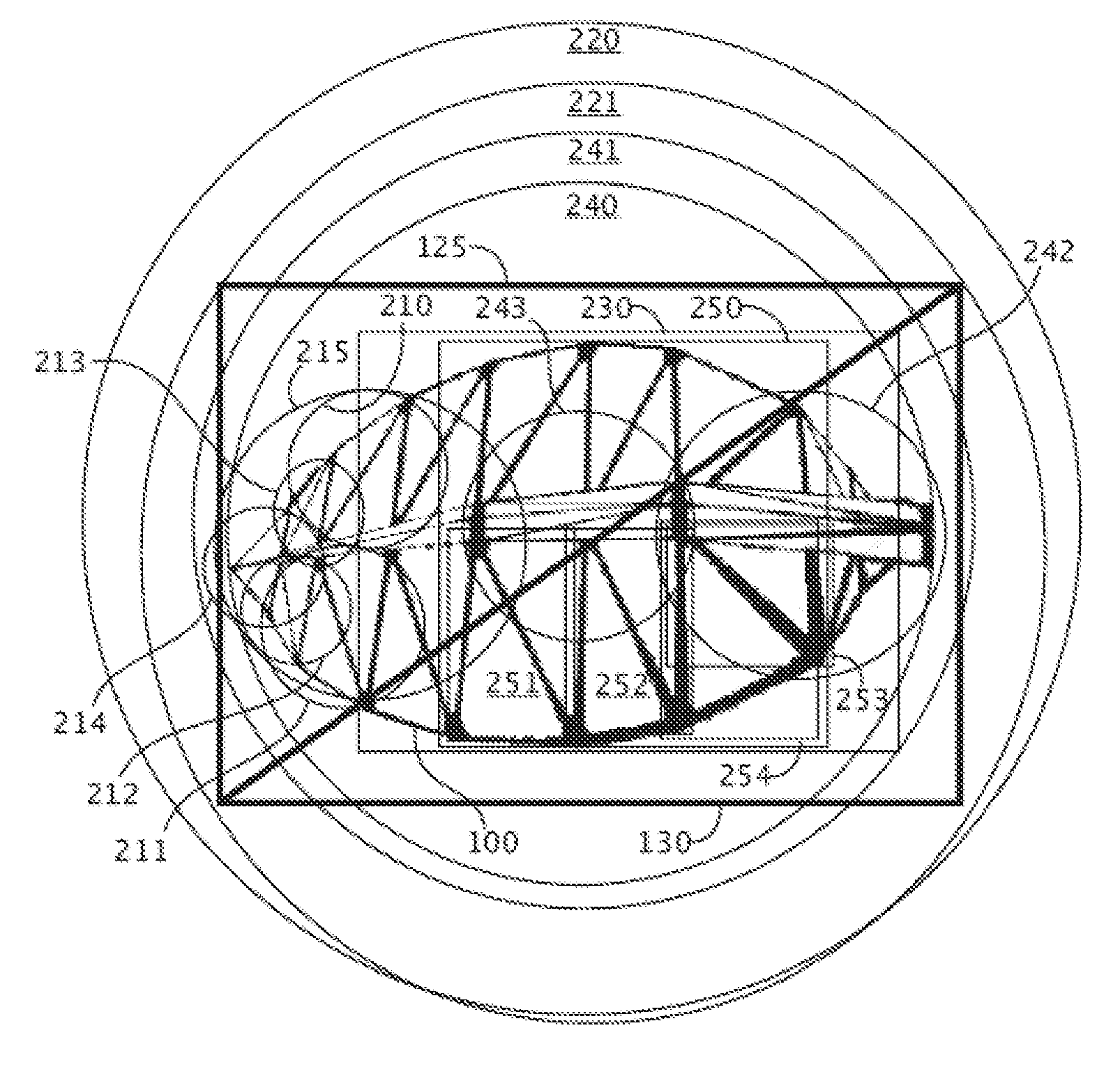
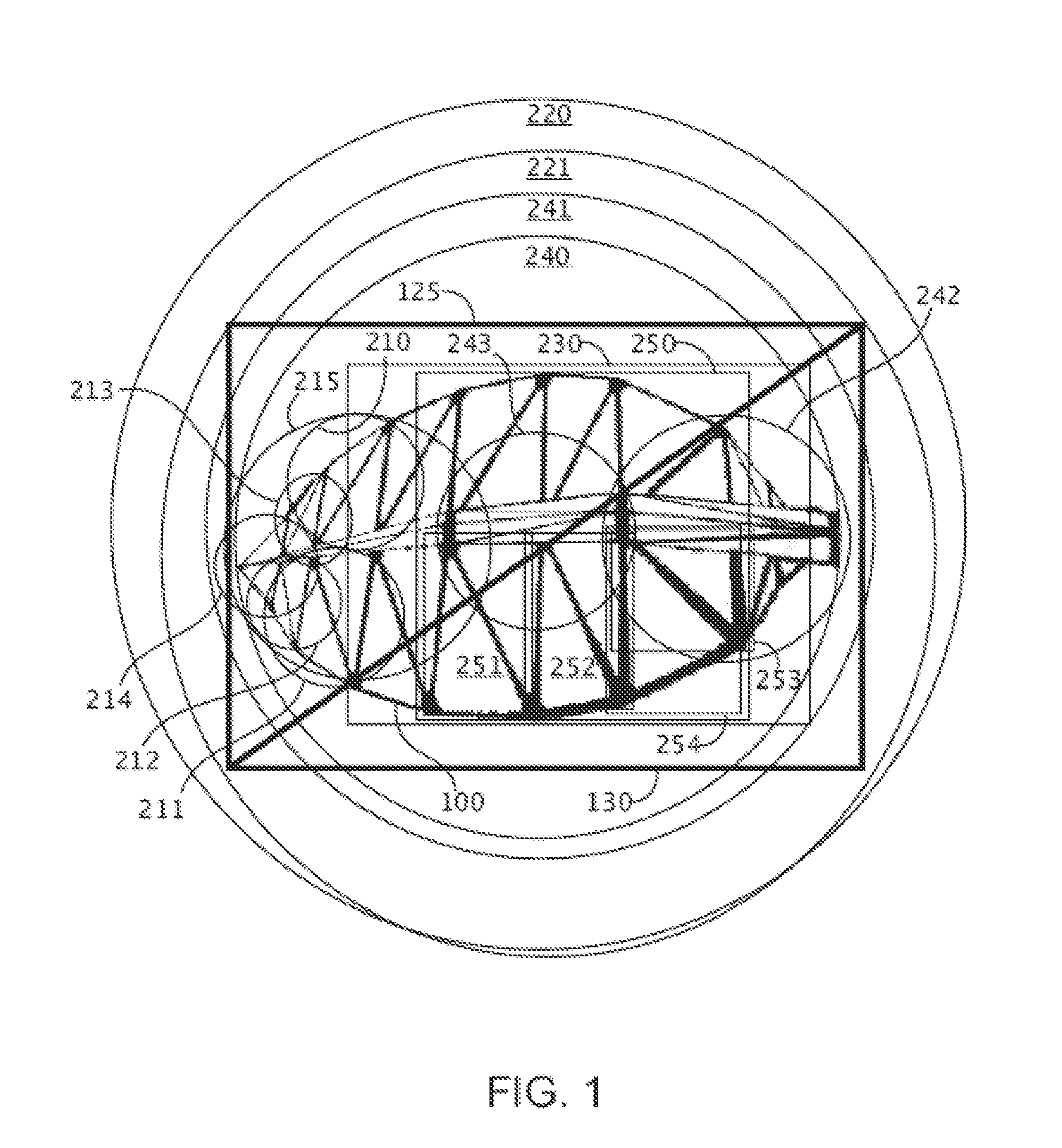
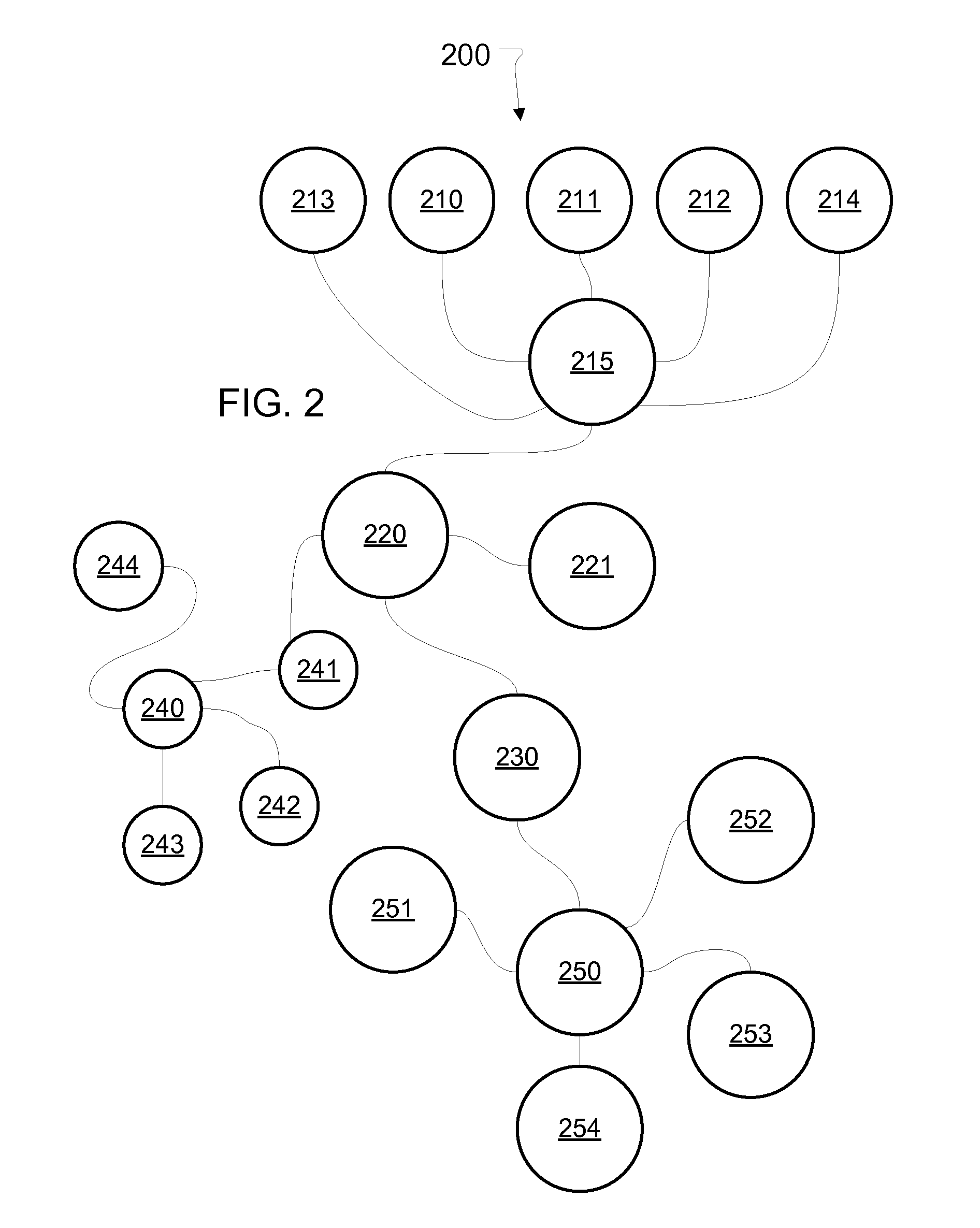
[0048]This description proceeds by introducing aspects relating to an example of a three-dimensional (3-D) scene (FIG. 1), that can be abstracted with geometry acceleration data, as in the example of FIG. 2. Such a 3-D scene can be rendered as a two-dimensional representation with systems and methods according to the examples illustrated and described. The systems comprise an intersection testing resource for accelerating identification of intersections between rays and primitives, and a host computing re...


PUM


Abstract

For ray tracing scenes composed of primitives, systems and methods accelerate ray / primitive intersection identification by testing rays against elements of geometry acceleration data (GAD) in a parallelized intersection testing resource. Groups of rays can be described as shared attribute information and individual ray data for efficient ray data transfer between a host processor and the testing resource. The host processor also hosts shading and / or management processes controlling the testing resource and adapting the ray tracing, as necessary or desirable, to meet criteria, while reducing degradation of rendering quality. The GAD elements can be arranged in a graph, and rays can be collected into collections based on whether a ray intersects a given element. When a collection is deemed ready for further testing, it is tested for intersection with GAD elements connected, in the graph, to the given element. The graph can be hierarchical such that rays of a given collection are tested against children of the GAD element associated with the given collection.

Description

BACKGROUND[0001]1. Field[0002]The present invention generally relates to rendering two-dimension representations from three-dimensional scenes, and more particularly to using ray tracing for accelerated rendering of photo-realistic two-dimensional representations of scenes.[0003]2. Description of Related Art[0004]Rendering photo-realistic images with ray tracing is well-known in the computer graphics arts. Ray tracing is known to produce photo-realistic images, including realistic shadow and lighting effects, because ray tracing models the physical behavior of light interacting with elements of a scene. However, ray tracing is also known to be computationally intensive, and at present, even a state of the art graphics workstation requires a substantial amount of time to render a complicated scene using ray tracing.[0005]Ray tracing usually involves obtaining a scene description composed of geometric primitives, such as triangles, that describe surfaces of structures in the scene, an...

Claims


Application Information

Patent Timeline
Patent Type & Authority Applications(United States)
IPC IPC(8): G06T15/20G06T15/06
CPCG06T2210/52G06T15/06
Inventor MCCOMBE, JAMES ALEXANDERSALSBURY, RYAN R.PETERSON, LUKE TILMAN
Owner IMAGINATION TECH LTD
Learn More