
Ultrasound Diagnostic Device Having Transducers Facing Each Other

a technology of array transducers and ultrasound, applied in tomography, instruments, applications, etc., can solve the problem of difficult to obtain ultrasound images with a high signal-to-noise ratio

Inactive Publication Date: 2009-05-21
SAMSUNG MEDISON
View PDF10 Cites 39 Cited by
  • Summary
  • Abstract
  • Description
  • Claims
  • Application Information

AI Technical Summary

Problems solved by technology

Thus, it is difficult to obtain an ultrasound image having a high signal-to-noise ratio (SNR) for a relatively far area from the transducer.

Method used


Image

  • Ultrasound Diagnostic Device Having Transducers Facing Each Other
  • Ultrasound Diagnostic Device Having Transducers Facing Each Other
  • Ultrasound Diagnostic Device Having Transducers Facing Each Other

Examples


Embodiment Construction

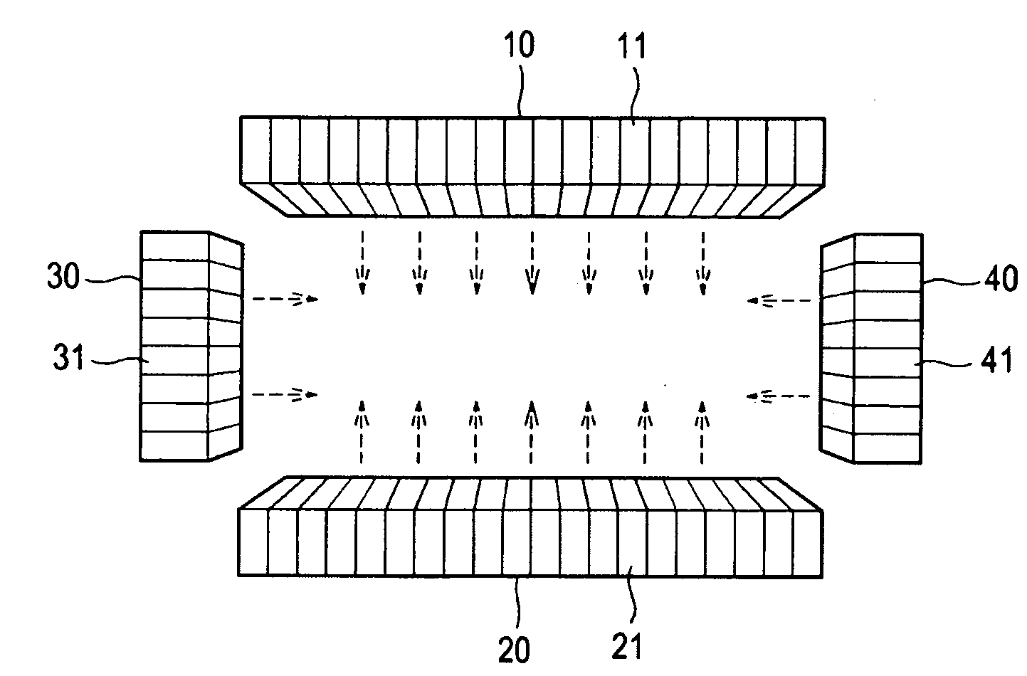
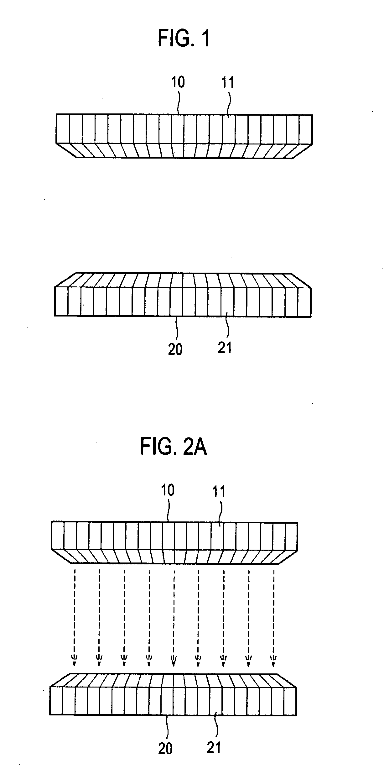
[0020]FIG. 1 is a schematic diagram showing an illustrative embodiment of a pair of transducers. As illustrated in FIG. 1, the ultrasound diagnostic device may include a pair of transducers 10 and 20. The pair of the transducers 10 and 20 may be arranged to face each other. The transducers 10 and 20 may be set apart from each other by a predetermined distance.

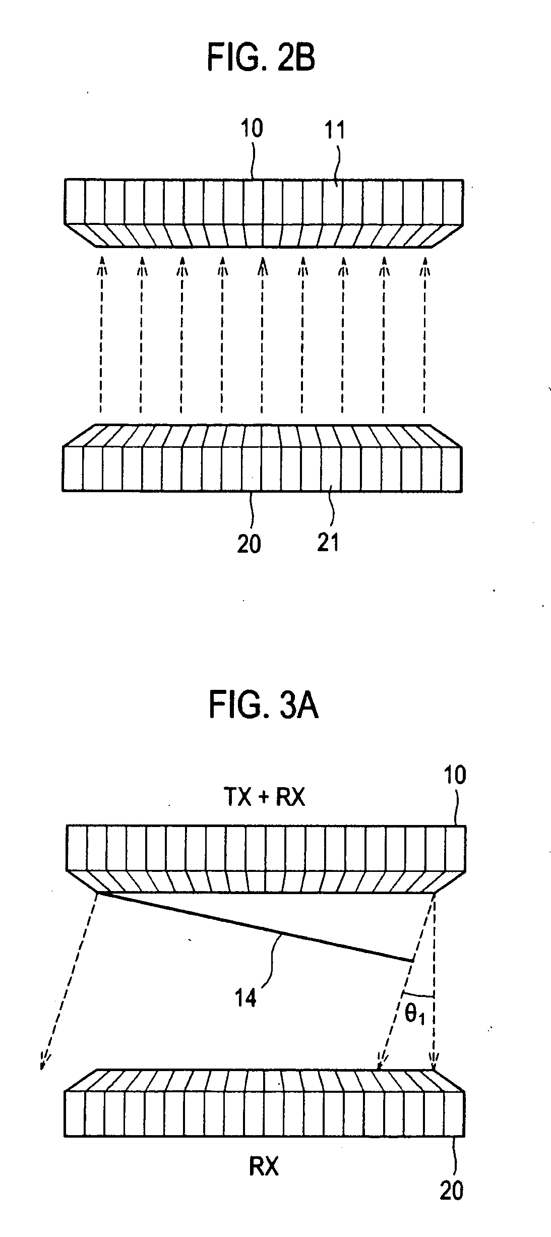
[0021]As illustrated in FIGS. 2A and 2B, each of the transducers 10 and 20 may have an array transducer having a plurality of elements 11 and 21. The elements 11 and 21 may transmit the ultrasound signals to a target object and receive ultrasound echoes reflected from the target object to thereby output analog receive signals. The transducers 10 and 20 may be a linear array transducer in which the elements are linearly arranged. A distance between two array transducers 10 and 20 may be adjustable by moving at least one of the transducers 10 and 20 in an axial direction. The distance may be adjusted according to the type of a ta...


PUM


Abstract

The present invention relates to an ultrasound diagnostic device. The ultrasound diagnostic device comprises a pair of transducers operable to transmit / receive ultrasound signals. The transducers are arranged to face each other. The transducers may be an array transducer including a plurality of elements, which are linearly arranged.

Description

[0001]The present application claims priority from Korean Patent Application No. 10-2007-0116168 filed on Nov. 14, 2007, the entire subject matter of which is incorporated herein by reference.BACKGROUND OF THE INVENTION[0002]1. Technical Field[0003]The present invention generally relates to an ultrasound diagnostic device, and more particularly to an ultrasound diagnostic device having a pair of array transducers facing each other.[0004]2. Background Art[0005]An ultrasound diagnostic device has become an important and popular diagnostic tool due to its non-invasive and non-destructive nature. The ultrasound diagnostic device may form an ultrasound image by utilizing wave characteristics of ultrasound such as reflection, scattering and absorption as ultrasound signals propagate through tissues of a human body. The ultrasound diagnostic device may have a transducer for transmitting ultrasound signals to a target object and receiving ultrasound echoes reflected back from it. An array t...

Claims


Application Information

Patent Timeline
IPC IPC(8): A61B8/15
CPCA61B5/0048A61B8/0825A61B8/15A61B8/463G01S15/8918A61B8/485A61B8/54G01S15/8929G01S15/8995A61B8/483A61B8/00
Inventor JEONG, MOK KUNKIM, YUNG GILKWON, SUNG JAEYOON, RA YOUNG
Owner SAMSUNG MEDISON
Learn More