Strainer system of snare drum and snare drum with the strainer system

a strainer system and snare drum technology, which is applied in the direction of instruments, percussion instruments, instruments, etc., can solve the problems of difficult operation of the strainer, noise easily occurring from the snare wire, and the inability to maintain the tension of the snare wire, so as to improve the operability of changing the position

Inactive Publication Date: 2009-05-28
HOSHINO GAKKI COMPANY LIMITED
View PDF16 Cites 16 Cited by
  • Summary
  • Abstract
  • Description
  • Claims
  • Application Information

AI Technical Summary

Benefits of technology

[0004]An objective of the present invention is to provide a strainer system of a snare drum which is improved in oper...

Problems solved by technology

As defects of this holding structure, the tension of the snare wire and the contact pressure of the snare wire with respect to the drumhead cannot be adjusted separately, and the tension of the snare wire makes it difficult to operate the strainer.
If the snare wire is spaced from the drumhead, the tension of the snare wire cannot be maintained, and noise easily occurs from the snare wire.
However, according to the methods disclosed in Japanese Utility Model Publication No. 43-22073 and U.S. Pat. No. 3,981,220, the frame is held with respect to the shell by using a belt or a string, so that although the snare wire can be brought into u...

Method used


Image

  • Strainer system of snare drum and snare drum with the strainer system
  • Strainer system of snare drum and snare drum with the strainer system
  • Strainer system of snare drum and snare drum with the strainer system

Examples


Embodiment Construction

[0015]Hereinafter, one embodiment of a strainer system of a snare drum of the present invention will be described with reference to FIGS. 1 to 7.

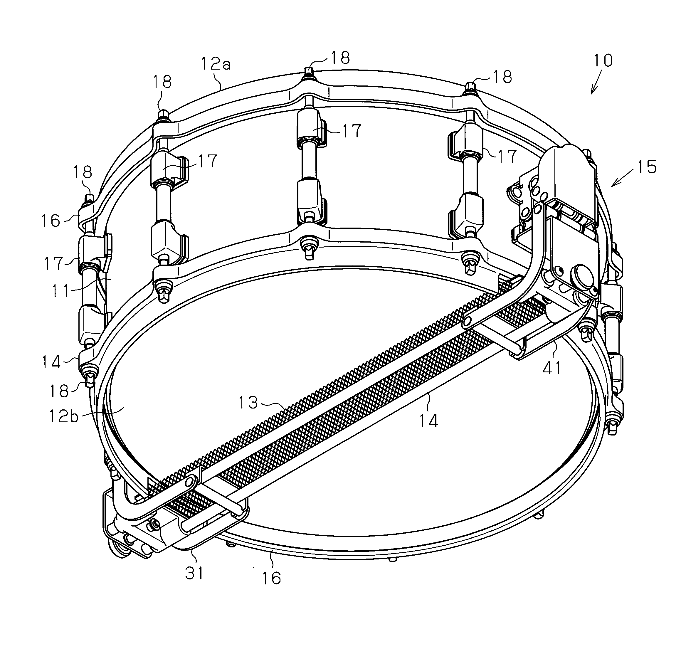
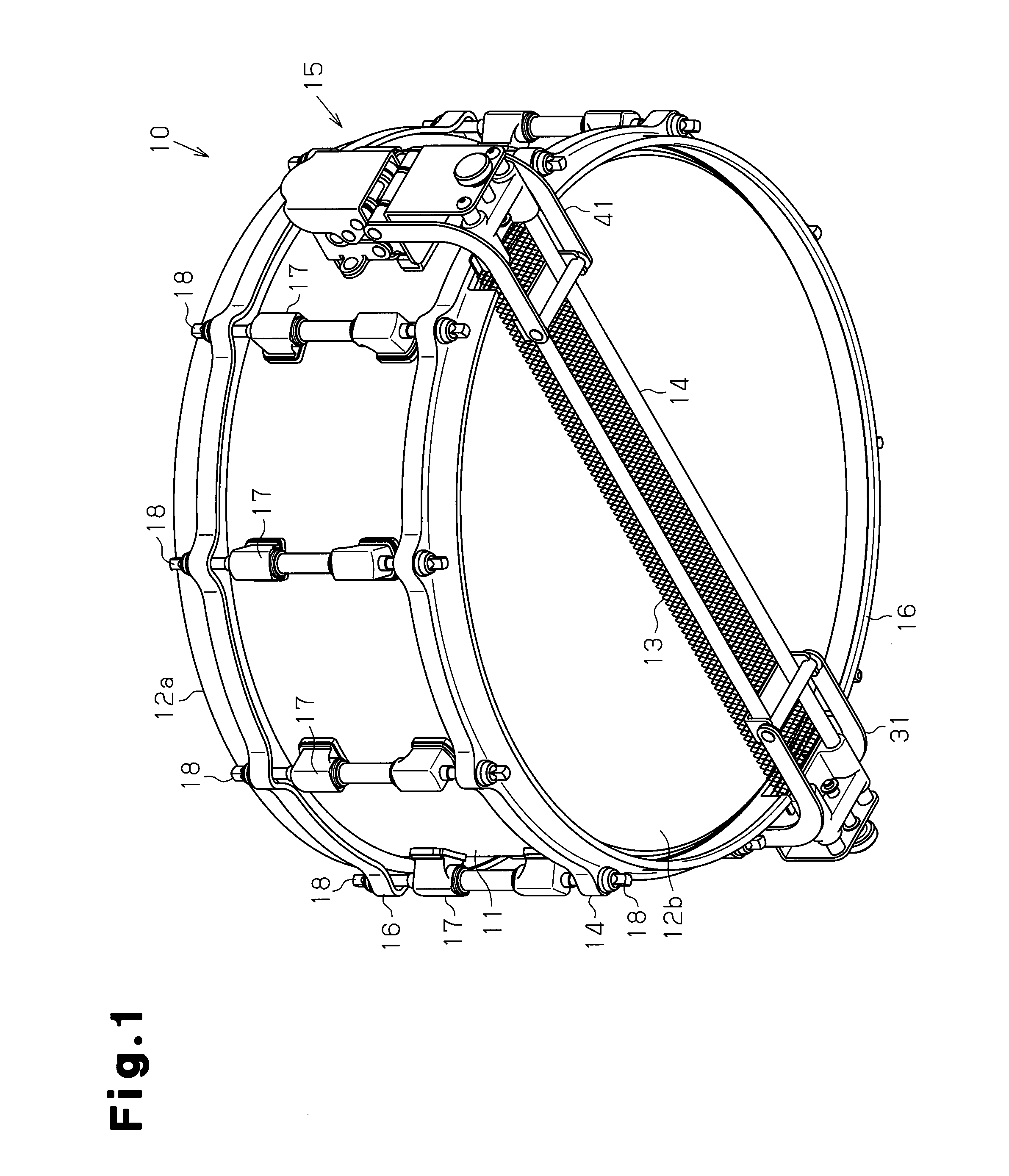
[0016]As shown in FIG. 1, the snare drum 10 includes a cylindrical shell 11, an upper drumhead 12a closing an upper open end of the shell 11, a lower drumhead 12b closing a lower open end of the shell 11, a snare wire 13 tensioned along the surface of the lower drumhead 12b, and a strainer system 15 which switches the position of the snare wire 13 between an OFF position spaced from the lower drumhead 12b and an ON position in contact with the lower drumhead 12b. When the upper drumhead 12a is beaten in a state that the position of the snare wire 13 is switched to the ON position, the snare wire 13 vibrates with the upper drumhead 12a and the lower drumhead 12b, and vibration sounds unique to the snare drum 10 are produced.

[0017]At both open ends of the shell 11, annular hoops 16 are provided, respectively. The respective drumheads 12a and ...


PUM


Abstract

A snare drum includes a strainer system which switches the position of a snare wire between an OFF position spaced from a lower drumhead and an ON position in contact with the lower drumhead. The strainer system includes a frame to which the snare wire is attached, and a pair of link mechanisms which are joined to the respective end portions of the frame and attach the respective end portions of the frame to a shell of the snare drum. After switching the position of the snare wire to the ON position, the position of the snare wire with respect to the lower drumhead is adjusted by operating an adjust screw of the second link mechanism.

Description

BACKGROUND OF THE INVENTION[0001]The present invention relates to a strainer system of a snare drum and a snare drum with the strainer system.[0002]A snare drum includes a cylindrical shell, a pair of drumheads fitted to the upper and lower open ends of the shell, and a snare wire tensioned along the surface of the lower drumhead. The snare wire vibrates when the drumhead is beaten in contact with the snare wire. As a structure for holding this snare wire with respect to the shell, a structure using a belt or a string is known. As defects of this holding structure, the tension of the snare wire and the contact pressure of the snare wire with respect to the drumhead cannot be adjusted separately, and the tension of the snare wire makes it difficult to operate the strainer. If the snare wire is spaced from the drumhead, the tension of the snare wire cannot be maintained, and noise easily occurs from the snare wire. To eliminate these defects, for example, Japanese Utility Model Public...

Claims


Application Information

Patent Timeline
IPC IPC(8): G10D13/02
CPCG10D13/025G10D13/18G10D13/02
Inventor MIYAJIMA, HIDEYUKI
Owner HOSHINO GAKKI COMPANY LIMITED
Why Eureka
Try Eureka