Sheet stacking device and image forming apparatus

a stacking device and stacking technology, applied in the direction of thin material processing, article delivery, function indicators, etc., can solve the problems of reducing productivity and inability to stop the upward movement of sheets, and achieve the effect of preventing damage to the devi

Active Publication Date: 2009-05-28
CANON KK
View PDF4 Cites 49 Cited by
  • Summary
  • Abstract
  • Description
  • Claims
  • Application Information

AI Technical Summary

Benefits of technology

[0016]In light of the above, the present invention provides a sheet stacking device and an image forming app

Problems solved by technology

Consequently, the image forming apparatus itself needs to be stopped to remove the sheet stack SA, leading to a reduction in productivity.
In the known stacker device 500, since the upper stopper limits the movement of the sheet stacking table 505 by having a direct contact therewith, the top of a sheet stack, if any, on the sheet stacking table 505 may bump into upper parts of the s

Method used


Image

  • Sheet stacking device and image forming apparatus
  • Sheet stacking device and image forming apparatus
  • Sheet stacking device and image forming apparatus

Examples


Embodiment Construction

[0036]Embodiments of the present invention will now be described in detail with reference to the drawings.

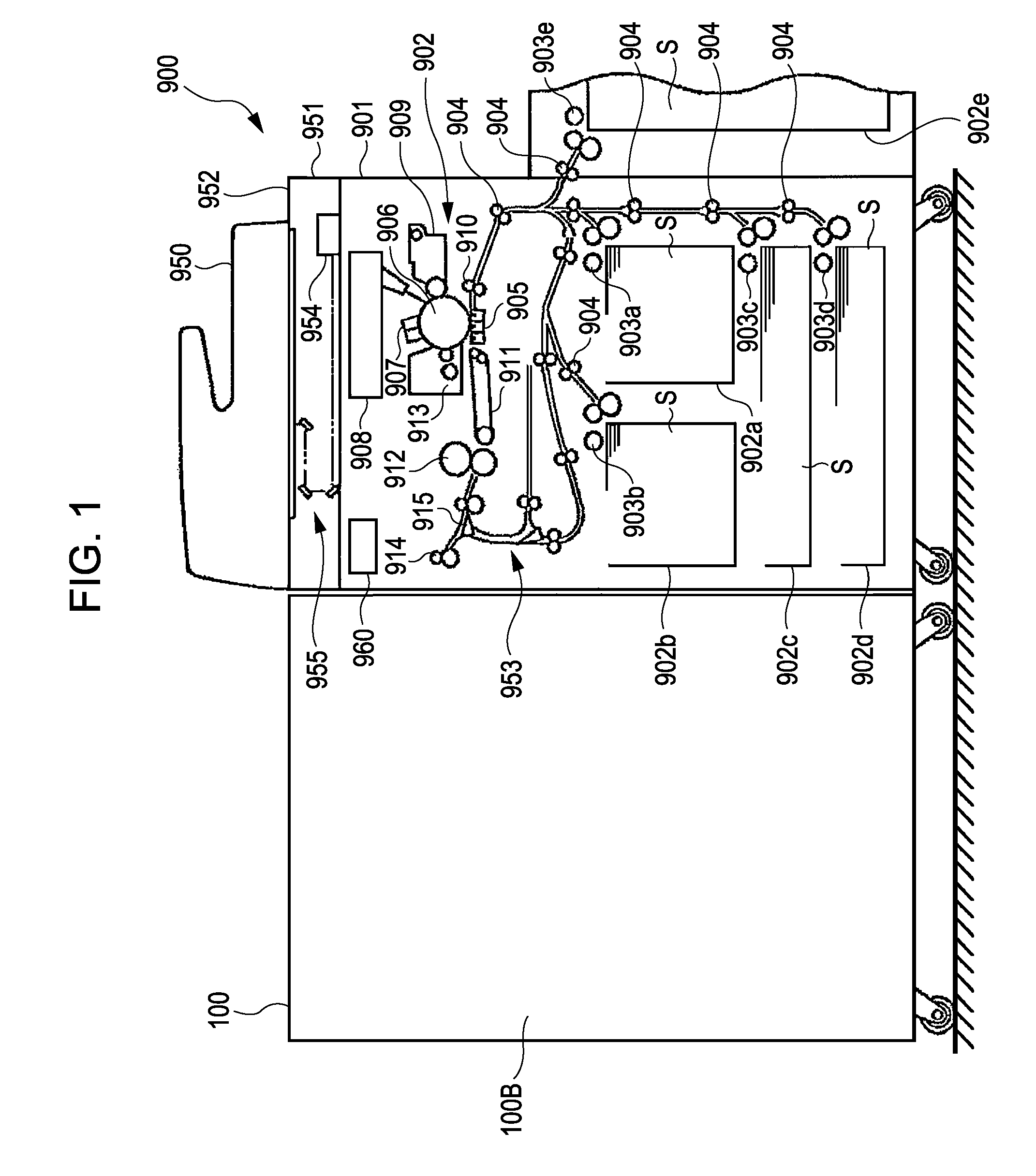
[0037]FIG. 1 shows an image forming apparatus including a sheet stacking device according to an embodiment of the present invention.

[0038]Referring to FIG. 1, an image forming apparatus 900 includes a body 901 and an image reader 951 disposed atop of the body 901. The image reader 951 includes a scanner unit and an image sensor 954. The image forming apparatus also includes a document feeder 950 disposed atop of the image reader 951. The document feeder 950 feeds a document to a platen glass 952.

[0039]The image forming apparatus 900 also includes in the middle section of the body 901 an image forming section that forms an image on a sheet and a sheet turner 953. The image forming section 902 includes a cylindrical photoconductive drum 906, a charger 907, a developer 909, a cleaner 913, and so forth. Further, a fuser 912, a pair of discharging rollers 914, and so forth are provid...


PUM

PropertyMeasurementUnit
Forceaaaaaaaaaa

Abstract

A stacker includes a plurality of sheet stacking units individually movable upward and downward. Sheets are selectively stacked onto either of the stacker trays. To remove the sheets stacked on one of the stacker trays, a door is opened. In a state where the door is open, the stacker trays moved by respective elevation units are movable only downward. In this manner, accidental upward movement of each of the stacker trays caused by a malfunction of a motor or the like is regulated, whereby damage to the stacker is prevented.

Description

BACKGROUND OF THE INVENTION[0001]1. Field of the Invention[0002]The present invention relates to sheet stacking devices in which a large number of sheets that are discharged thereto can be stacked and image forming apparatuses including such sheet stacking devices.[0003]2. Description of the Related Art[0004]With the advancement in technology, recently developed image forming apparatuses form images on sheets at an increasing speed. With such an increase in image forming speed, the speed of discharging sheets from the body of an image forming apparatus is also increasing. For the purpose of aligning and stacking a large number of sheets that are discharged at a high speed, there are some image forming apparatuses each including a large-capacity stacker device, a sheet stacking device, as disclosed in Japanese Patent Laid-Open No. 2006-124052.[0005]FIG. 17 shows an exemplary known large-capacity stacker device. A stacker device 500 includes a gripper 503 that is attached to a conveyi...

Claims


Application Information

Patent Timeline
IPC IPC(8): B65H29/00
CPCB65H31/18B65H2301/131B65H2402/45B65H2405/15B65H2405/331B65H2407/10B65H2511/20B65H2801/06B65H2220/01B65H2220/11B65H2220/02B65H2405/3311
Inventor OBUCHI, YUSUKEFUKATSU, YASUOWATANABE, NAOTO
Owner CANON KK
Why Eureka
Try Eureka