Load monitoring method and load monitoring apparatus for kneading apparatus

a monitoring method and kneading technology, applied in the direction of measuring devices, instruments, force/torque/work measurement apparatus, etc., can solve the problems of screw shaft fracture, fatigue fracture of shaft, no consideration,

Active Publication Date: 2009-05-28
KOBE STEEL LTD
View PDF1 Cites 14 Cited by
  • Summary
  • Abstract
  • Description
  • Claims
  • Application Information

AI Technical Summary

Benefits of technology

[0049]By the load monitoring method and apparatus of the present i...

Problems solved by technology

In the extruder of the Japanese patent laid-open publication 2000-225641, however, no consideration is given to the case where a repetitive load of a degree not exceeding the designed mechanical strength is imposed on the screw shaft and causes fatigue fracture of the shaft.
Therefore, even if operation is continued in such a manner that the load does not exceed the designed mechanical strength of the screw shaft, there is a fear that the screw shaft may be fractured by fatigue fra...

Method used


Image

  • Load monitoring method and load monitoring apparatus for kneading apparatus
  • Load monitoring method and load monitoring apparatus for kneading apparatus
  • Load monitoring method and load monitoring apparatus for kneading apparatus

Examples


second embodiment

[0101]A load monitoring method and a load monitoring apparatus according to a second embodiment of the present invention will be described below.

[0102]As shown in FIG. 5, the load monitoring method according to this second embodiment is different from the first embodiment in that in connection with performing both issuance of the “abnormal” alarm 22 and stop of rotation of the screw shafts 3, there newly is provided a second set time tb shorter than the set time ts and set within one minute, the “abnormal” alarm 22 is issued when the overload duration time t0 exceeds the second set time tb, and thereafter, when the overload duration time t0 exceeds the set time ts, the rotation of the screw shafts 3 is stopped.

[0103]The load monitoring method according to this second embodiment is carried out in accordance with steps S51 to S59. In this case, the steps S51 to S55 are carried out in the same way as in the steps S41 to S45 in the first embodiment. But the step S56 and subsequent steps...

third embodiment

[0110]A load monitoring method and a load monitoring apparatus according to a third embodiment of the present invention will be described below.

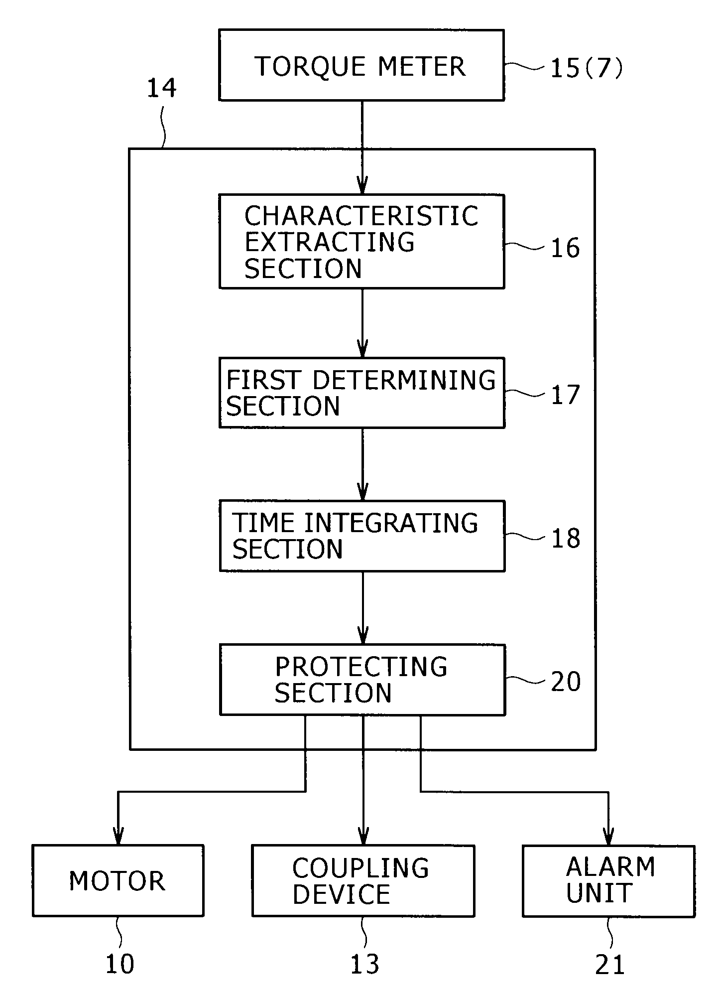
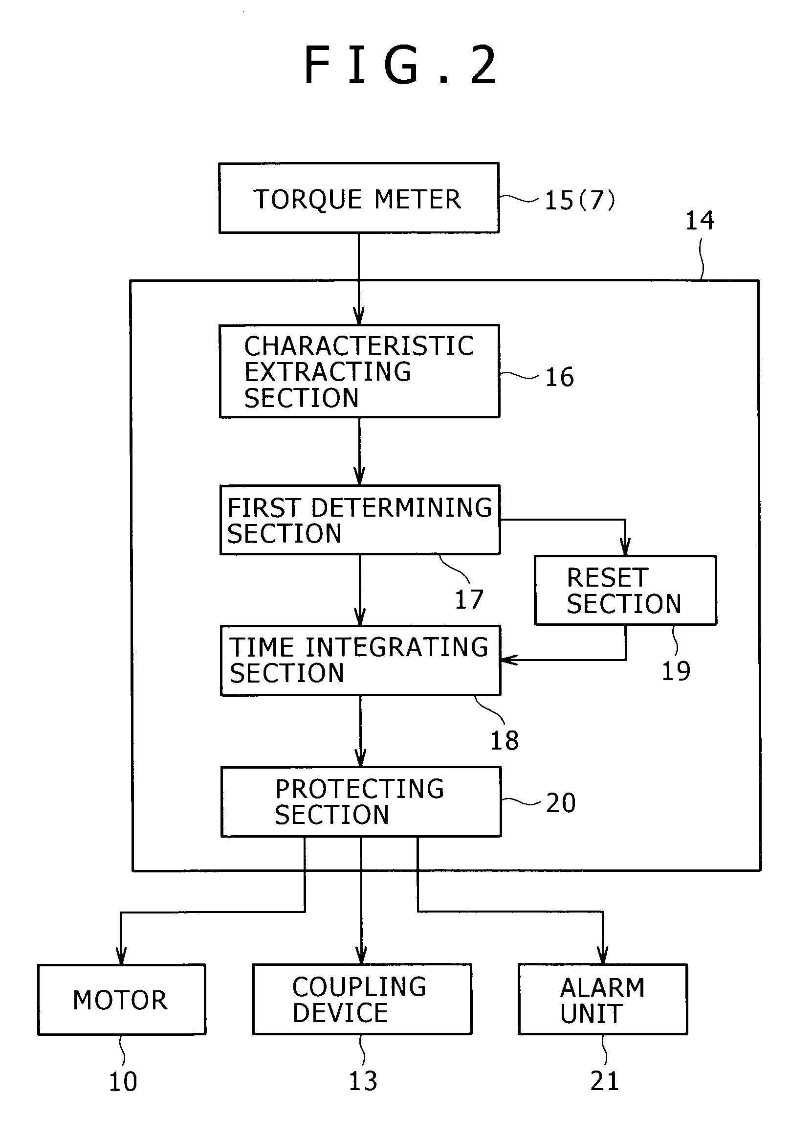
[0111]As shown in FIG. 6, the load monitoring method according to this third embodiment is different from the first embodiment in that the issuance of the “abnormal” alarm 22 and / or the stop of rotation of the screw shafts 3 are (is) performed when the detected value of torque T exceeds a predetermined abnormal value. In a controller 14 according to this third embodiment, as shown in FIG. 9, there is accordingly provided a second determining section 31 which determines whether the detected value of torque T has exceeded a predetermined abnormal value.

[0112]More particularly, the second determining section 31 in the controller 14 according to this third embodiment determines whether the detected value of torque T corresponds to a mechanical strength designed for the screw shafts 3 or more. A signal indicating a determination result of the tor...

fourth embodiment

[0121]A load monitoring method and a load monitoring apparatus according to a fourth embodiment of the present invention will be described below.

[0122]As shown in FIG. 7, the load monitoring method according to this fourth embodiment is different from the first embodiment in that a load mean value Ta is given beforehand as a fixed value instead of averaging detected values of torque T over the predetermined time section S to determine a load mean value Ta. Therefore, in the load monitoring apparatus according to this fourth embodiment there is used a fixed value inputted beforehand to the load mean value Ta as in FIG. 10.

[0123]The load monitoring method according to this fourth embodiment is carried out in accordance with the steps S71 to S77.

[0124]First, in each torque meter 15 there are detected values of torque T in the same way as in S41 in the first embodiment [S71].

[0125]Next, a load amplitude value Tw is calculated on the basis of the detected values of torque T inputted from...


PUM

PropertyMeasurementUnit
Mechanical strengthaaaaaaaaaa

Abstract

In an extruder or a kneader, load (torque T) values on an input shaft portion of a screw shaft are detected by a load detector installed on the input shaft portion, then an overload condition is determined from a load mean value (Ta) and a load amplitude value (Tw) of the detected load values, and the issuance of an “abnormal” alarm and/or the stop of rotation of the screw shaft are (is) performed when an overload duration time (t0) of maintaining the overload condition exceeds a set time (ts). In this way the screw shaft is protected from fatigue fracture caused by application thereto of such a load as does not exceed a designed mechanical strength but causes fatigue fracture.

Description

BACKGROUND OF THE INVENTION[0001]1. Field of the Invention[0002]The present invention relates to a load monitoring method and a load monitoring apparatus for monitoring a load imposed on a screw shaft of a kneading apparatus such as an extruder or a kneader.[0003]2. Description of the Related Art[0004]A kneading apparatus such as a kneader or an extruder includes a barrel having a long hollow portion in its axial direction, a screw shaft for kneading a material to be kneaded which is fed into the barrel, and a drive unit for rotating the screw shaft. The screw shaft has kneading blades for kneading the material to be kneaded.[0005]In kneading, if the material to be kneaded is not in a thoroughly melted state or is difficult to be kneaded, a load larger than a designed strength may be imposed on the screw shaft. In conventional kneading apparatus, a load monitoring apparatus is used lest a load larger than a designed strength should be imposed on the screw shaft.[0006]For example, in...

Claims


Application Information

Patent Timeline
IPC IPC(8): G08B21/00B29C48/03B29C48/92
CPCB29C47/0009G01L5/0071B29C47/92B29C2947/92038B29C2947/92066B29C2947/92095B29C2947/92295B29C2947/92304B29C2947/9239B29C2947/92457B29C2947/92542B29C2947/9259B29C2947/9279B29C2947/92885B29C2947/92952B29C2947/9298B29C47/0801B29C48/92B29C48/03B29C48/252B29C2948/92038B29C2948/92066B29C2948/92095B29C2948/92295B29C2948/92304B29C2948/9239B29C2948/92457B29C2948/92542B29C2948/9259B29C2948/9279B29C2948/92885B29C2948/92952B29C2948/9298B29B7/488B29B7/728B29B7/48
Inventor YAMAGUCHI, KAZUOYAMANE, YASUAKIKASAI, SHIGEHIROHONKE, KOICHI
Owner KOBE STEEL LTD
Why Eureka
Try Eureka