Part fatigue fracture evaluating apparatus, part fatigue fracture evaluating method, and computer program

a fatigue fracture and evaluating method technology, applied in the direction of measuring devices, material strength using repeated/pulsating forces, instruments, etc., can solve the problem of stress in the portion with the highest risk of fatigue fractur

Inactive Publication Date: 2013-11-14
NIPPON STEEL CORP
View PDF2 Cites 9 Cited by
  • Summary
  • Abstract
  • Description
  • Claims
  • Application Information

AI Technical Summary

Benefits of technology

[0017]According to the present invention, it is designed to derive an index for evaluating fatigue inside a machine part based on the product of a probability distribution function of an inclusion size and the size of a region of the part where a stress amplitude of an acting stress exceeds a fatigue strength. Thus, it is possible to make a fatigue design of the machine part in consideration of both a distribution of an inclusion existing inside the machine part and a distribution of an internal stress of the machine part.

Problems solved by technology
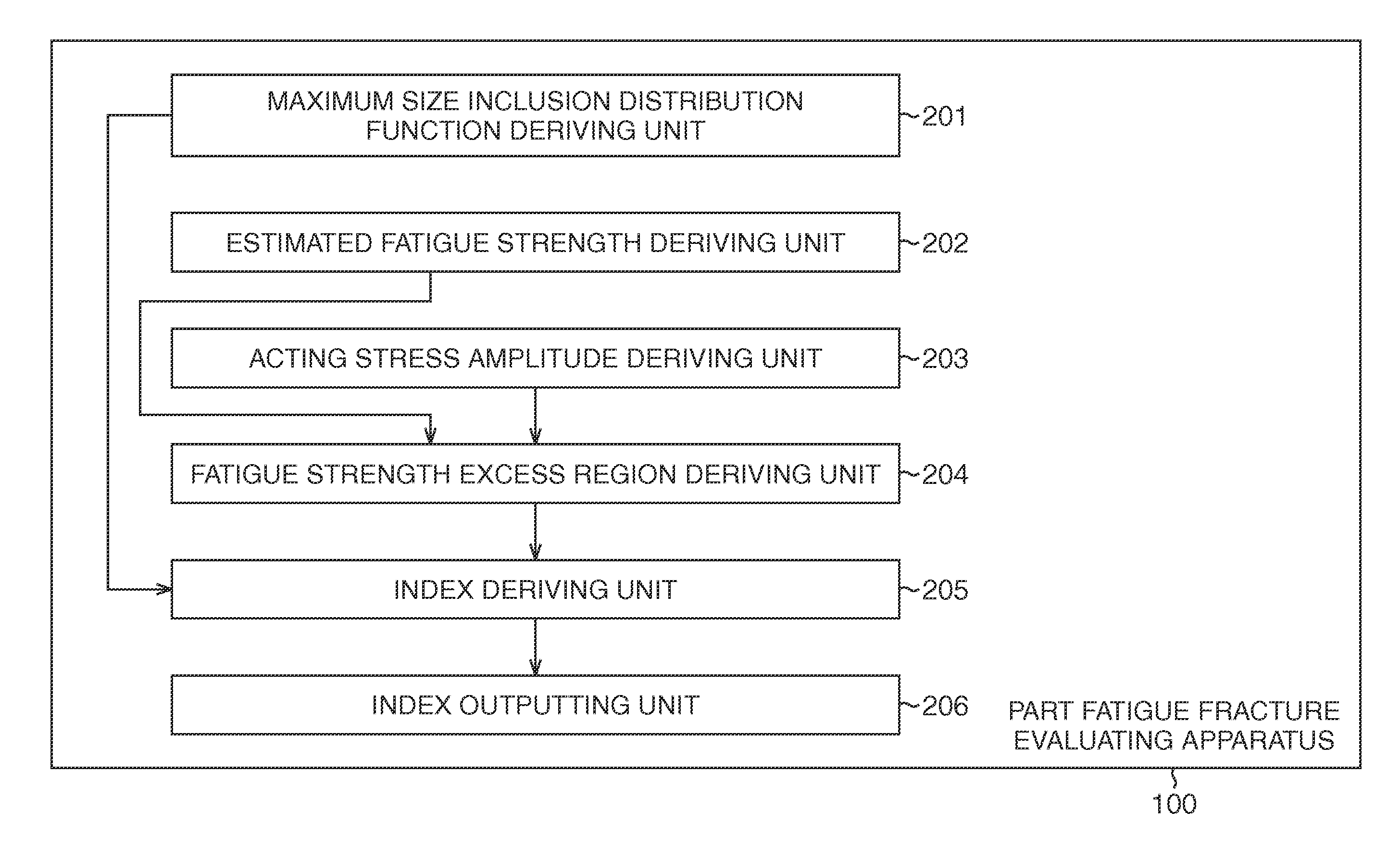
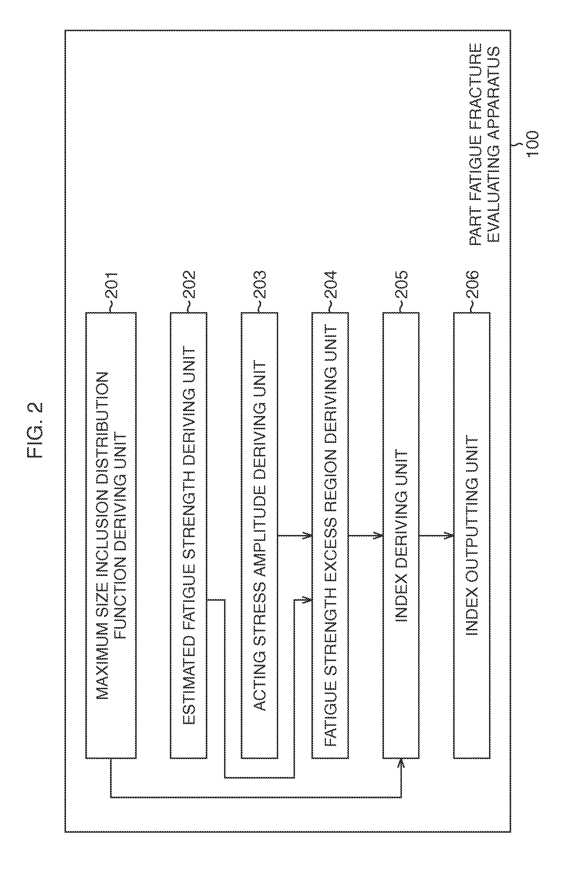
Further, in this method, as the stress to act on the part, the stress in a portion having the highest risk of fatigue fracture is only evaluated.

Method used


Image

  • Part fatigue fracture evaluating apparatus, part fatigue fracture evaluating method, and computer program
  • Part fatigue fracture evaluating apparatus, part fatigue fracture evaluating method, and computer program
  • Part fatigue fracture evaluating apparatus, part fatigue fracture evaluating method, and computer program

Examples


example 1

[0116]Next, examples of the present invention will be explained. First, as Example 1, the example in the case where the stress amplitude σ of the acting stress is a stress amplitude τa (r) of a shear stress will be explained.

[0117]In this example, as the part, a coil spring having had a compressive residual stress introduced to a surface thereof was used. As the material constituting the coil spring, a high-tensile spring steel having a strength of 1800 [MPa] class (the Vickers hardness Hv=627) was used. This material is known that fatigue fracture stating from an inclusion existing inside the material occurs. Here, r of the stress amplitude τa (r) of the shear stress represents a distance from the center of a wire of the coil spring in a circumferential direction of the coil spring.

[0118]In this example, coil springs having a wire diameter of 3.3 [mm], an outer diameter of 22 [mm], and the numbers of windings of 30 and 6 were made of this material. Each of these coil springs had a ...

example 2

[0146]Next, Example 2 will be explained. In Example 2, there will be explained the example in the case when a rotary bending test in which a test piece is rotated while loading bending moment thereto and an axial tensile repeated stress to be increased in a surface direction from the axial center is caused to occur is performed.

[0147]In this example, a round bar test piece having had a compressive residual stress introduced to a surface thereof was used. As the material constituting the round bar test piece, a SUP12 (a silicon chromium steel) defined as a spring steel in JIS was used. The Vickers hardness Hv of this material is 550.

[0148]In this example, round bar test pieces having parallel portions of 10 [mm] and 50 [mm] in length, a parallel portion of 4 [mm] in diameter, and a grip portion of 12 [mm] in diameter were made of the above material. Each of these round bar test pieces had a similar shot peening process performed thereon and had a residual stress introduced to a surfa...

example 3

[0164]Next, Example 3 will be explained. In this example, similarly to Example 2, there will be explained the example in the case when a rotary bending test in which a test piece is rotated while loading bending moment thereto and an axial tensile repeated stress to be increased in a surface direction from the axial center is caused to occur is performed.

[0165]In this example as well, a round bar test piece having had a compressive residual stress substantially similar to that in Example 2 introduced to a surface thereof was used. As the material constituting the round bar test piece, a defined material similar to that in Example 2 was used. However, while the Vickers hardness Hv of the material used in Example 2 is 550, the Vickers hardness Hv of this material is 530.

[0166]In this example as well, round bar test pieces having parallel portions of 10 [mm] and 50 [mm] in length, a parallel portion of 4 [mm] in diameter, and a grip portion of 12 [mm] in diameter were made of the above...


PUM

PropertyMeasurementUnit
fatigue fractureaaaaaaaaaa
sizeaaaaaaaaaa
sizesaaaaaaaaaa

Abstract

There is derived an index FS (P) obtained by integrating the product of a probability distribution function f (√{square root over ( )}areamax) of an inclusion size √{square root over ( )}areamax of a part and a “size S (P, √{square root over ( )}√{square root over ( )}areamax) of a region of the part” where a stress amplitude σ of an acting stress exceeds a stress amplitude σw of a fatigue strength at each location in the case of a load being applied under a loading condition P set previously by an operator over the inclusion size √{square root over ( )}√{square root over ( )}areamax of the part with the whole region of a range where a probability distribution of the inclusion size √{square root over ( )}areamax exists set as an integral range.

Description

TECHNICAL FIELD[0001]The present invention relates to a part fatigue fracture evaluating apparatus, a part fatigue fracture evaluating method, and a computer program and, particularly to, those that are preferably used to evaluate fatigue inside a machine part subjected to a repeated load.BACKGROUND ART[0002]Conventionally, design of machine parts (metal parts and the like) subjected to a repeated load is often made to prevent fatigue fracture thereof. As a conventional typical method for determining an allowable stress for fatigue of such a part, there is a method described in Non-Patent Literature 1 in terms of a spring. Normally, as fatigue characteristics of a material, the allowable stress is determined in each steel type, and thus the method described in Non-Patent Literature 1 is designed to determine the allowable stress by using the steel type. However, as for a steel type in which the allowable stress is not determined, and a special one, their allowable stresses are deter...

Claims


Application Information

Patent Timeline
Patent Type & Authority Applications(United States)
IPC IPC(8): G01N3/02
CPCG01N3/02G01N3/32G01N2203/0067G01N2203/0073G01N2203/0218
Inventor SHIMANUKI, HIROSHI
Owner NIPPON STEEL CORP
Why Eureka
Try Eureka