Rotating apparatus with a torque limiter function

a technology of torque limiter and rotating apparatus, which is applied in the direction of gearing, piston pumps, hoisting equipments, etc., can solve the problems of increasing the difficulty of theoretical analysis of stress, increasing the difficulty of fatigue breakage (fatigue fracture) at a torque, and increasing the factor s

Active Publication Date: 2007-12-25
DENSO CORP
View PDF16 Cites 9 Cited by
  • Summary
  • Abstract
  • Description
  • Claims
  • Application Information

AI Technical Summary

Benefits of technology

[0013]To solve the above problems, the present invention is aimed primarily to provide a rotating apparatus having a novel torque limiter function different from the conventional one and secondarily to prevent the power transmission at a predetermined torque.

Problems solved by technology

However, fatigue breakage (fatigue fracture) occurs at a torque smaller than the breaking torque, as is well known.
In general, the safety factor S must be made larger as theoretical analysis of the stress is made more difficult due to a complicated state of stress that occurs in a structure.
As the shearing force tends to be concentrated on a surface, it is difficult to precisely calculate and analyze the stress distribution.
In a structure similar to the above-mentioned rotating apparatus, because the dimension and the material, etc. of the breakable part must be determined by trial and error, there are difficulties in designing and developing the same and the actual breaking torque varies, thus leading to a fear of malfunction of the torque limiter such as an occurrence of breakage of the breakable part by twisting at a torque lower than the breaking torque.

Method used


Image

  • Rotating apparatus with a torque limiter function
  • Rotating apparatus with a torque limiter function
  • Rotating apparatus with a torque limiter function

Examples


embodiment 4

[0080 will be explained below. According to this embodiment, as shown in FIG. 7, the shaft 1a is comprised of two shafts 1n and 1m which are connected in series through a screw engagement and the engaging torque of the screw engagement portion 1p of the shafts 1n and 1m is a torque determined based on the maximum torque during a normal operation of the compressor 1, taking into account a predetermined safety factor.

[0081]With this structure, as in Embodiments 1 through 3, when the sliding part of the compressor is stuck due to burning, etc., the tightening torque at the screw engagement portion 1p is increased in accordance with an increase in the torque transmitted to the pulley 9, to thereby increase the tensile axial force. Consequently, when the tensile axial force acting on the breakable part 1i is above the axial tension equivalent to the breaking torque, the breakable part 1i is broken to interrupt the transmission of the torque.

[0082]According to this embodiment, the lug pla...

embodiment 2

[0083]According to this embodiment, the shaft 1m is provided with the breakable part 1i which is broken when the tensile axial force is above the axial tension equivalent to the breaking torque. However, , it is possible that, when the tensile axial force is above an axial tension equivalent to the breaking torque, the screw engagement portion 1p is broken so as to interrupt the torque transmission, by setting the strength of the screw engagement portion 1p such that the screw thread can be stripped and broken when a predetermined tightening torque larger than the engaging torque is applied thereto.

[0084]As is apparent from the above explanation, according to this embodiment, the shaft 1m, the shaft 1n and the breakable part 1i correspond to “an input side rotating member”, “an output side rotating member” and “a breakable part” respectively, which are described in claims.

embodiment 5

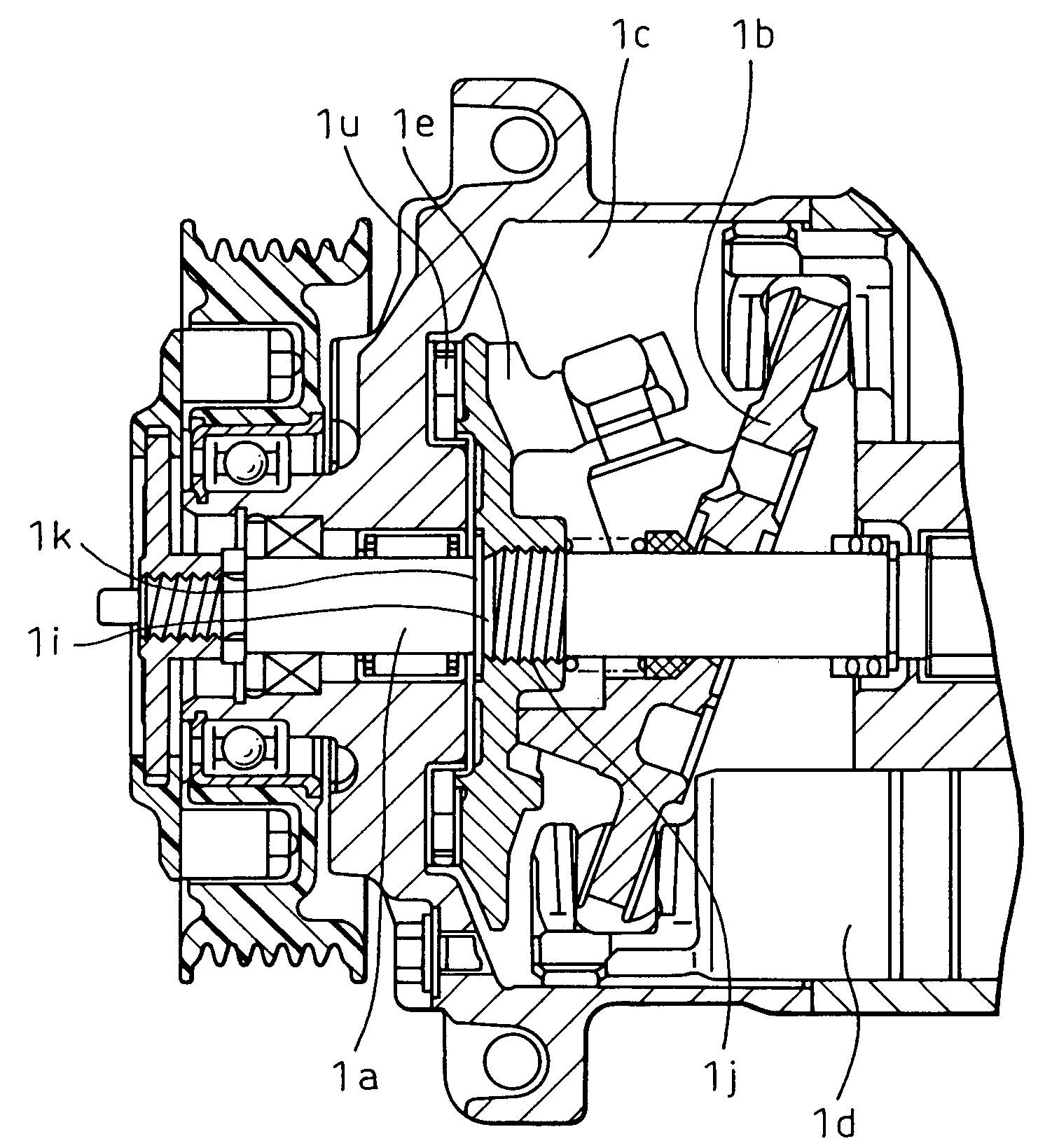
[0085 will be explained below. According to this embodiment, as shown in FIG. 8, the lug plate 1e is provided with a bridge 1r which forms an easily breakable part whose mechanical strength is reduced. In the concrete, the lug plate 1e is comprised of a hub 1s secured to the shaft 1a, an outer periphery 1t located on the outer peripheral side and connected to the swash plate 1b, and the bridge 1r connecting the hub 1s to the outer periphery 1t. When the sliding part of the compressor is stuck due to burning, etc., the bending moment acts on the bridge 1r.

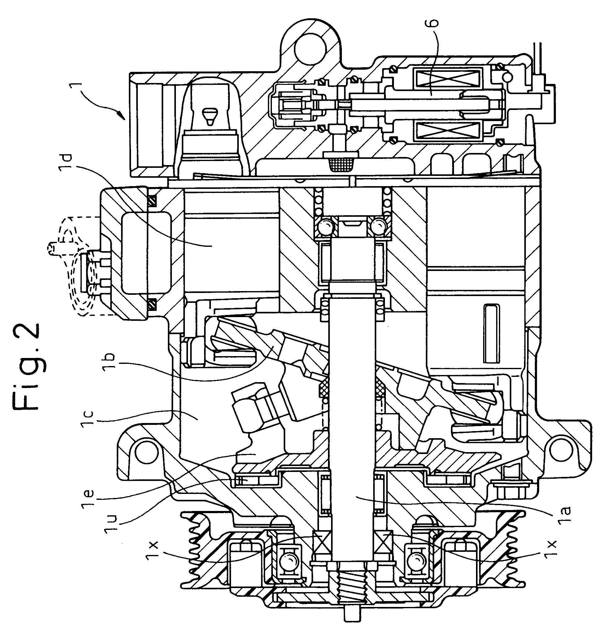
[0086]That is, the lug plate 1e rotates while receiving a bending moment about the thrust bearing 1u (see FIG. 2, etc.), from the shaft 1a. Thus, when the sliding part of the compressor is stuck due to burning, etc., the bending moment about the thrust bearing 1u is increased in accordance with an increase in the torque transmitted to the pulley 9, to thereby increase the bending moment acting on the bridge 1r. Consequently, the br...


PUM


Abstract

A screw engagement portion between a pulley and a shaft is provided with a thread in a direction to increase the tightening torque when the pulley is driven. A breakable part broken by the axial tension produced when the tightening torque acting on the screw engagement portion is above a predetermined value, is also provided. The stress to break the breakable part is mainly a tensile stress. The tensile stress is substantially uniformly distributed in a cross section and, hence, the stress distribution of the breakable part can be relatively precisely predicted and analyzed. Consequently, the necessity of determining aspects of the breakable part, such as dimension, material, and the like, by trial and error is reduced. The breakable part can be broken without being subject to fatigue fracture.

Description

BACKGROUND OF THE INVENTION[0001]1. Field of the Invention[0002]The present invention relates to a rotating apparatus with a torque limiter function and is advantageously applicable to a compressor of a vapor-compression type refrigerator for a vehicle.[0003]2. Description of the Related Art[0004]A compressor of a vapor-compression type refrigerator for a vehicle is powered by the engine for moving the vehicle. The compressor or a pulley driven by a belt has a torque limiter function to prevent transmission of the torque when the transmission torque is above a predetermined value, in order to protect devices and components, such as a belt, provided on the drive source side, when a sliding part of the compressor is stuck due to burning, etc.[0005]In a conventional, rotating apparatus with a torque limiter function, a breakable part whose diameter is smaller than those of the remaining portion is provided on a shaft of the compressor, so that the breakable part can be preferentially t...

Claims


Application Information

Patent Timeline
Patent Type & Authority Patents(United States)
IPC IPC(8): F16H61/00F04B27/14F04B35/00F16D9/00F16D9/08F16H35/10F16H55/36
CPCF16D9/08
Inventor NOSAKA, MICHIYASUTATEMATSU, SHOZOUEDA, MOTOHIKOHASHINAGA, KOICHI
Owner DENSO CORP
Why Eureka
Try Eureka