Vent valve

a technology of vent valves and valve housings, applied in the field of vent valves, can solve the problems of increased valve housing height, unsuitable construction for use, and a certain amount of internal pressure for outlet seals

Inactive Publication Date: 2009-06-04
BWANOLAR
View PDF14 Cites 24 Cited by
  • Summary
  • Abstract
  • Description
  • Claims
  • Application Information

AI Technical Summary

Benefits of technology

[0018]The invention will be more fully understood in light o

Problems solved by technology

A disadvantage of vent valves of the form described above is that, when used on sewer mains, in order to prevent foreign matter present in the water fouling the seals, the height of the valve housing is increased significantly in order to provide an air gap between the water level in the housing and the seals when the valve is pressurised rendering these constructions unsuitable for use where height limitation apply which is a common occurrence in underground sewer mains.
A further disadvantage is that the outlet seals require a certain amount of internal pressure, normally twenty kilopascals in order to achieve an effective seal.
In some cases when the mains are charged full but the pumps are not running the

Method used


Image

  • Vent valve
  • Vent valve
  • Vent valve

Examples


Embodiment Construction

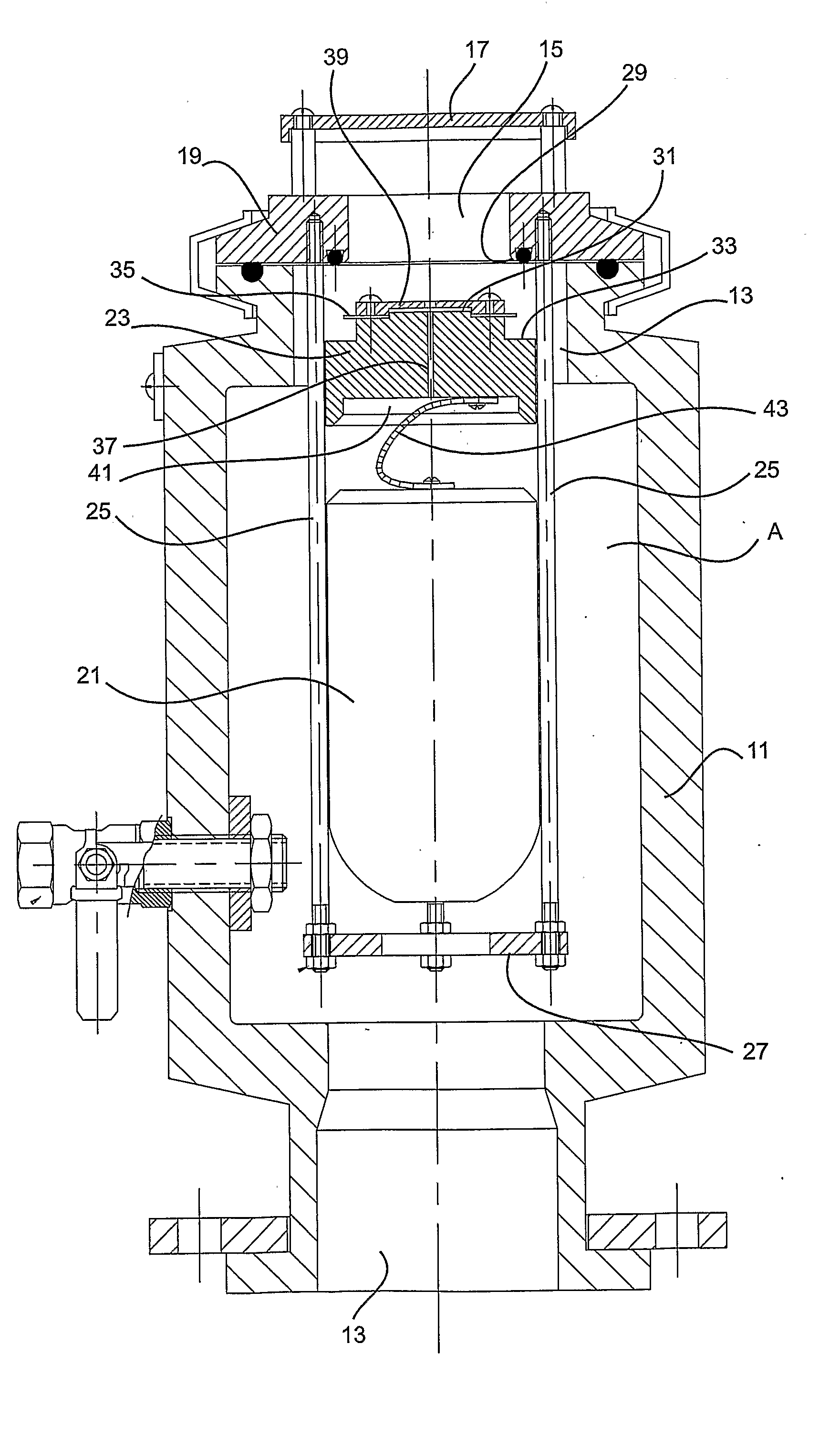
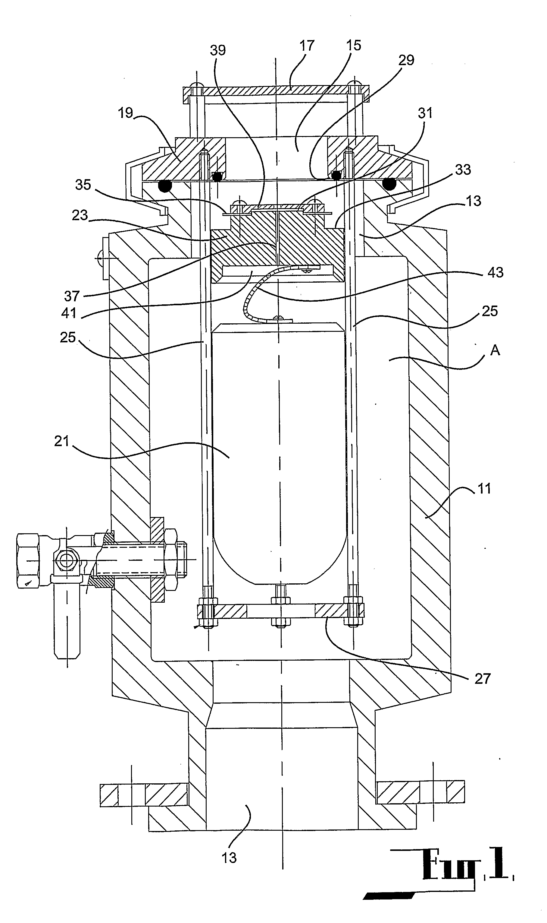
[0029]Each of the embodiments are directed to a vent valve which can be utilised in a fluid line to enable air or gases contained within the fluid line to be vented from the fluid line when the fluid line is pressurised and in use and to enable the entry of air into the fluid line on a low pressure condition being created within the fluid line. The vent valve according to the embodiment has application for use in fluid lines which carry entrained debris and materials such as sewerage.

[0030]It is an object of the vent valve according to each of the embodiments to provide an arrangement whereby the sealing between the valve body and the outlet of the vent valve is isolated from the fluid liquid contained within the vent valve and fluid line and any debris entrained therein to reduce the likelihood of the failure of the valve due to any of the entrained debris becoming engaged with the sealing surfaces between the valve body and the outlet.

[0031]The first embodiment as shown at FIGS. 1...


PUM


Abstract

A pipeline vent valve comprising a body (11) defining a chamber of clerestory configuration in which the upper portion (B) of the chamber is of reduced cross-sectional area, the chamber having an inlet (13) towards its lower end which is adapted to be connected to a pipeline and an outlet (15) in the upper portion, a valve body (23) supported in the upper portion of the chamber to be movable between a first position at which it is in sealing engagement with the outlet and a second position at which it is out of sealing engagement with the valve seat, said valve body being responsive to the level of liquid in the chamber in the chamber and being adapted to close on the liquid level in the chamber exceeding a predetermined level, said valve body having central passage (37) providing communication to each side of the valve body, a float member (21) supported within the chamber and adapted to cause said movement of said valve body between the first and second position as a result of the presence of liquid in the chamber, the float member being further adapted sealingly engage said central passage as the liquid in the chamber reaches the predetermined level and to and expose said passage on relative movement of the float member away from the valve body.

Description

FIELD OF THE INVENTION[0001]This invention relates to vent valves which are utilised in pipelines for releasing of air and other gases from the pipeline in order to prevent the formation of air pockets at high points along a pipeline which would otherwise restrict the flow of water through the pipeline. In particular the invention relates to those valves which are known as combined air release valves which are designed to vent or admit large quantities of air whilst the pipeline is being filled and emptied and to continuously release small amounts of air which accumulate in the pipeline in use and specifically relates to those valves which are used on extremely contaminated water service such as sewer mains.BACKGROUND ART[0002]Several types of air release valves are known. The first type commonly termed an automatic air release valve releases air which is accumulated under-pressure in a pipeline during normal operating conditions. In this type of valve a float member is located with...

Claims


Application Information

Patent Timeline
IPC IPC(8): F16K24/04
CPCF16K24/044F16K31/24F16K24/06Y10T137/3099
Inventor HERLIHY, GEOFFREY FRANCIS
Owner BWANOLAR
Why Eureka
Try Eureka