Wire/cable identification device

a technology of identification device and wire/cable, which is applied in the direction of identification means, cables, insulated conductors, etc., can solve the problems of ineffective identification, considerable difficulties, and inconvenient production, and achieves the effect of simple structure and easy production

Active Publication Date: 2009-06-04
BRIDGEPORT FITTINGS LLC +2
View PDF19 Cites 20 Cited by
  • Summary
  • Abstract
  • Description
  • Claims
  • Application Information

AI Technical Summary

Benefits of technology

[0009]Another object is to provide for a plurality of wire identification devices in an arrangement whereby the individual identification devices can be readily dispensed as needed.
[0013]Another object is to provide a wire identifier which is relatively simple in structure, easy to produce and positive in operation.

Problems solved by technology

In the electrical arts, and in particular in areas wherein electrical wires and / or cables are being installed in buildings and / or in other installations requiring numerous terminals and / or wires or cables to be installed at remote locations, considerable difficulties have been encountered in the order and / or to what circuit a given wire or cable is to be connected.
The difficulty encountered with such practice rendered such identification ineffective in the event another installer or electrician would later be required to complete, repair and / or alter a given wiring installation, e.g. in a residential or commercial building.
In the event any repairs at some future time were required, considerable difficulties have been encountered in determining which wire or cable is causing a circuit or an electric appliance to malfunction.
Such labels have limited application in that in a finished construction, the labels would not be visible as the label would be within a closed wall or behind a junction box or panel.
An apparent disadvantage of a “clip on” type tag or marker is that over time, such “clip on” markers are prone to also “clip off”, causing the associated wire to lose its identification.

Method used


Image

  • Wire/cable identification device
  • Wire/cable identification device
  • Wire/cable identification device

Examples


Embodiment Construction

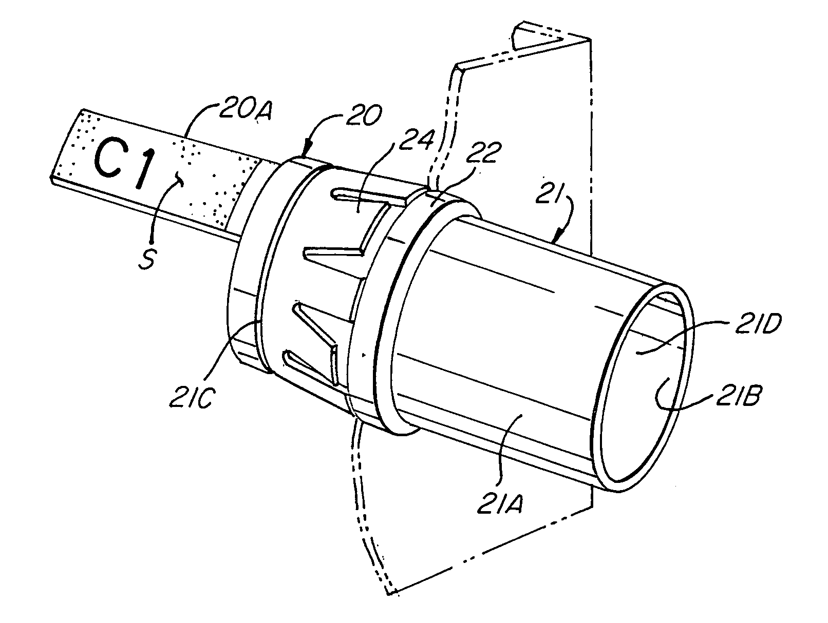
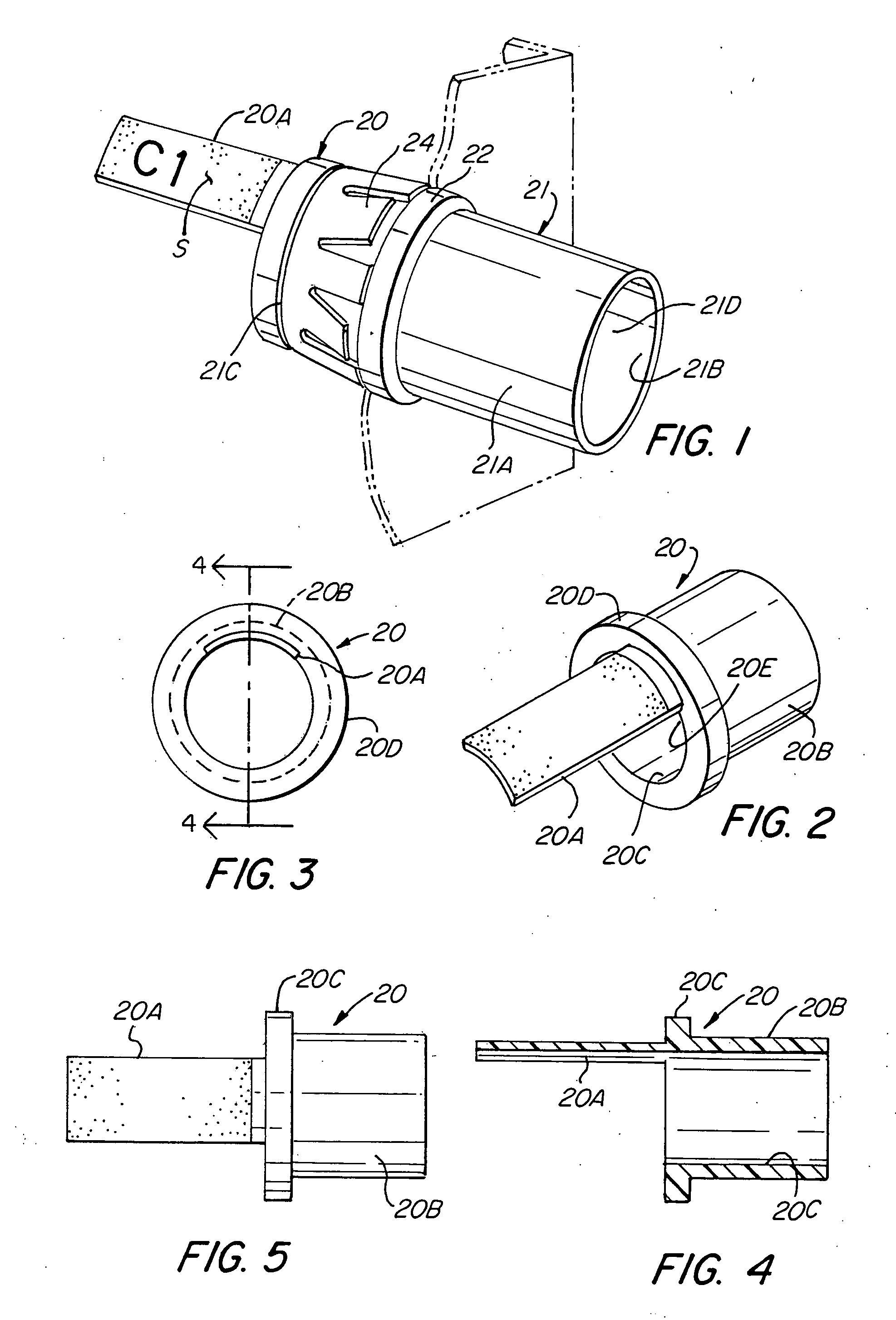
[0030]Referring to the drawings, there is illustrated in FIGS. 1 to 5, a first embodiment of the invention. As shown in FIG. 1, the wire identifier 20 is illustrated as applied to an electrical connector 21 of any standard or known construction. Such electrical connectors generally have a connector body 21A formed with an inlet end portion 21B, an outlet end portion 21C and a bore 21D extending therethrough. Such electrical connectors are arranged to receive a wire conductor, cable or the like as exemplified in U.S. Pat. Nos. 2,744,769; 1,483,218; 6,555,750 B2, and other patents that are used to connect associated wire conductors or cables to a knock-out hole of an electric box or panel. Generally, the known connectors include a radially outwardly extending flange 22 circumscribing the connector body 21 intermediate the inlet end portion 21B and the outlet end portion 21C to limit the insertion of the connector body through a knock-out hole of an electric box or panel. In the illust...


PUM

PropertyMeasurementUnit
non-electrical conductingaaaaaaaaaa
color codeaaaaaaaaaa
sizesaaaaaaaaaa

Abstract

An electric wire identifier that includes an anti-short bushing in the form of an electrical insulating ring-like insert fitted onto the end of a metal or armored clad cable that defines the terminal end of the armored cable or into the end of an electrical connector that is generally inserted through a knock-out hole of an electric box or panel, and which bushing includes an integral extension or surface capable of retaining thereon suitable identifying indicia that is rendered visible throughout the lifetime of the electrical installation. In another form of the invention, the wire identifiers, in the form of a label or tag having a loop attachment that may be arranged in a tree or roll whereby the individual labels or tags can be readily dispensed as needed.

Description

FIELD OF THE INVENTION[0001]This invention relates to identification devices, and more specifically to an electric wire or cable identifier.BACKGROUND OF THE INVENTION[0002]In the electrical arts, and in particular in areas wherein electrical wires and / or cables are being installed in buildings and / or in other installations requiring numerous terminals and / or wires or cables to be installed at remote locations, considerable difficulties have been encountered in the order and / or to what circuit a given wire or cable is to be connected. Generally, it was the installer's practice to mark a given wire or cable in a makeshift manner with whatever means available by which the installer could identify which wire or cable was to be connected to a particular circuit or terminal. Thus, each installer would create his or her own personal identification arrangement which, over time, may fade or disappear. The difficulty encountered with such practice rendered such identification ineffective in ...

Claims


Application Information

Patent Timeline
Patent Type & Authority Applications(United States)
IPC IPC(8): H01B7/36B65C3/02B65C9/34
CPCB65C3/02H01R11/28G09F3/0295
Inventor SMITH, LAWRENCE J.
Owner BRIDGEPORT FITTINGS LLC
Why Eureka
Try Eureka