Fluid filled type vibration damping device

a technology of vibration damping device and fluid filling, which is applied in the direction of shock absorbers, machine supports, mechanical equipment, etc., can solve the problems of difficult to achieve effective vibration damping action of fluid filling type vibration damping device of known construction

Inactive Publication Date: 2009-06-04
SUMITOMO RIKO CO LTD
View PDF7 Cites 23 Cited by
  • Summary
  • Abstract
  • Description
  • Claims
  • Application Information

AI Technical Summary

Benefits of technology

[0010]It is therefore one object of this invention to provide a fluid filled type vibration damping device of novel construction, that is able to effectively exhibit vibration damping effect based on the flow action of the fluid through the orifice passage against vibration over a wider frequency range and is realized by a simple construction.

Problems solved by technology

Therefore, they may suffer from a problem that effective vibration damping action will not be attained against vibration to be damped depending on errors in frequency of vibration to be damped, and individual difference in tuning of orifice passages due to manufacturing errors, dimensional errors, material errors and so forth of the fluid filled type vibration damping devices.
However, it is difficult for fluid filled type vibration damping devices of known construction to exhibit vibration damping effect based on the flow action of the fluid through the orifice passage over a wide frequency range, although they are able to adjust tuning frequency by means of appropriately setting the ratio of passage length and passage cross sectional area of the orifice passages etc.
In particular, the fluid filled type vibration damping devices of simple construction without outside control mechanism such as electromagnetic oscillation members have not yet been realized the art that attains both effective vibration damping effect and effective wide frequency range at the same time.

Method used


Image

  • Fluid filled type vibration damping device
  • Fluid filled type vibration damping device
  • Fluid filled type vibration damping device

Examples


first embodiment

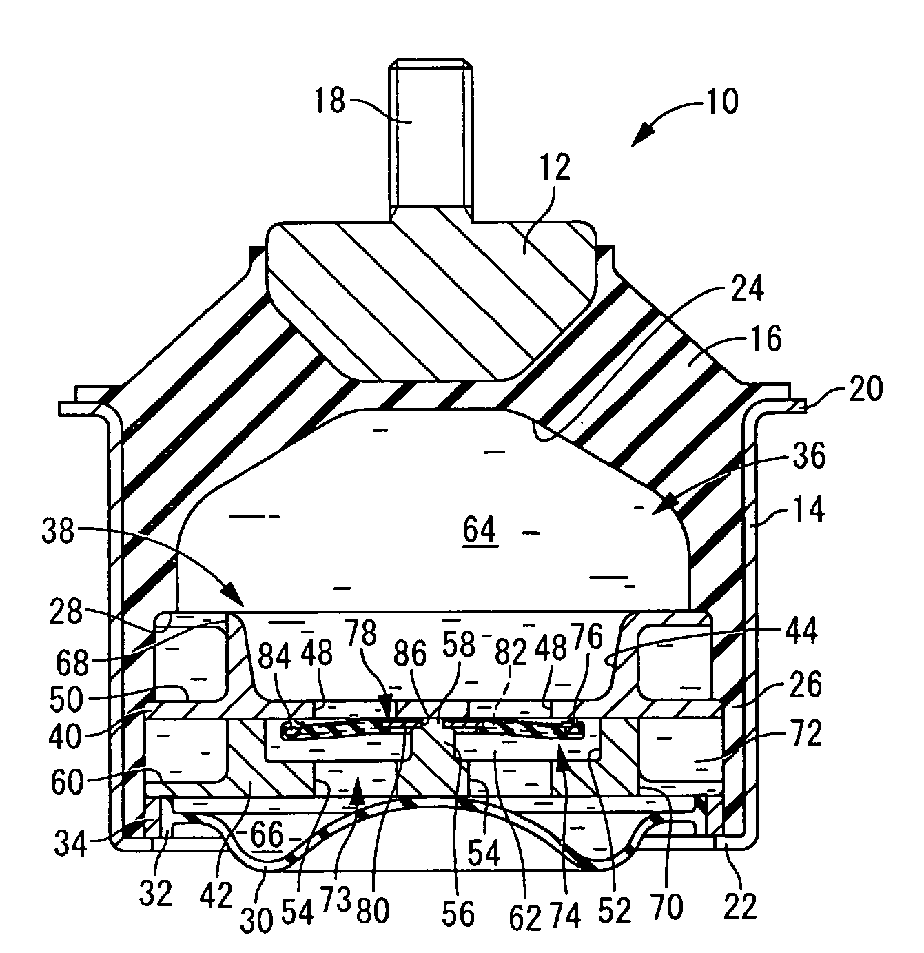
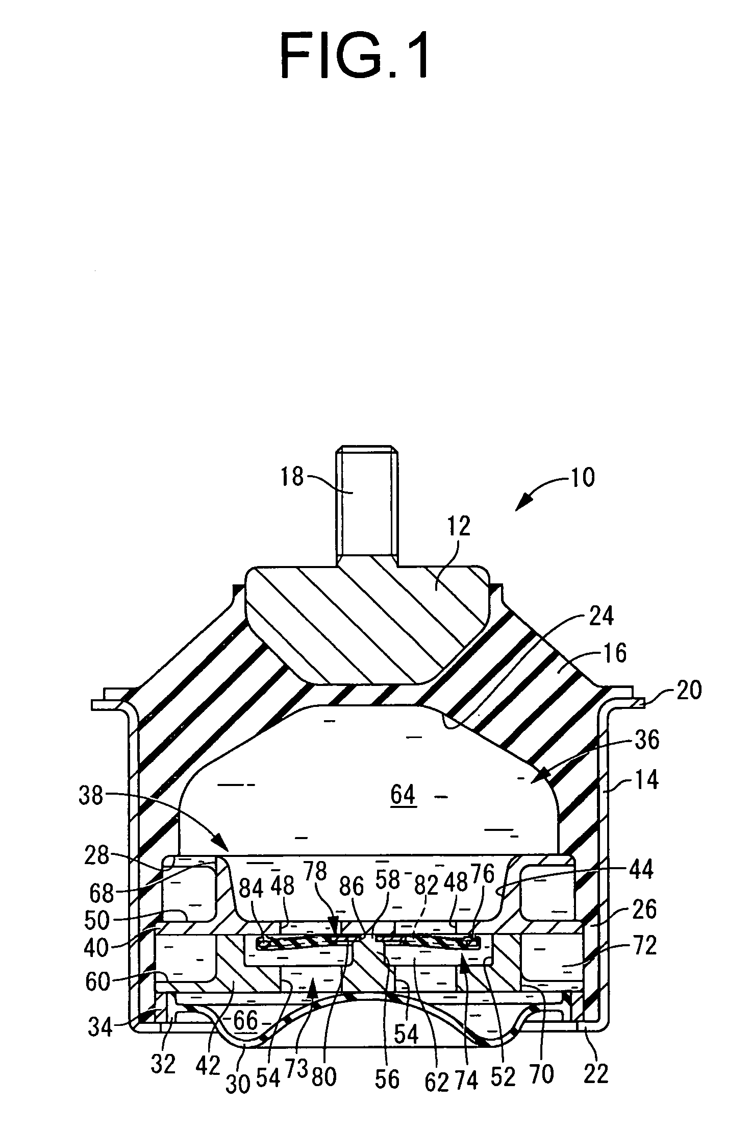
[0126]As in the first embodiment described previously, the partition member 90 will be fastened supported with its outside peripheral face in intimate contact against the second mounting member 14, by being inserted within the second mounting member 14, and in this state subjecting the second mounting member 14 to a diameter reduction process.

[0127]With the partition member 90 installed in the second mounting member 14, the opening of the circumferential groove 98 that was formed at the outside peripheral edge of the partition member main body 92 will be covered by the cover fitting 94. A tunnel-like passage that extends in the circumferential direction through the outer peripheral section of the partition member 90 is formed thereby. Furthermore, at locations corresponding to the circumferential ends of the circumferential groove 98, an upper connecting passage 68 is formed in the cover fitting 94, while a lower connecting passage 70 is formed in the partition member main body 92. ...

second embodiment

[0166]The moveable rubber film 170 having the above structure will be arranged housed within a housing space 102 of a partition member 176. The partition member 176 has a thick, large-diameter, generally circular disk shape, and includes a partition member main body 178 and a cover fitting 180. The partition member main body 178 and the cover fitting 180 have structures in accordance with those of the partition member main body 154 and the cover fitting 94 taught in the The diametrically medial section of the cover fitting 180 is perforated by an upper communication window 182 that extends for a prescribed length in circumferential direction and serves as a communication passage, while a lower communication window 184 that extends for a prescribed length in circumferential direction is formed in the diametrically medial section of the partition member main body 178. Also, the diametrical center section of the cover fitting 180 is perforated by an upper through-hole 186 of circular ...


PUM


Abstract

A fluid filled type vibration damping device including: a partition member having a communication passage connecting a pressure receiving and equilibrium chambers; an obstructing rubber elastic plate juxtaposed against the communication passage from an equilibrium chamber side, adapted to obstruct the communication passage, and arranged to be exposed to pressure of the pressure receiving and the equilibrium chamber at both faces; and a constraining member provided for retaining an outer peripheral section of the obstructing rubber elastic plate in contact against the partition member at multiple locations. The constraining member provides an opening / closing control member operated to induce the obstructing rubber elastic plate to push against the partition member and close off the communication passage, and to induce elastic deformation of the obstructing rubber elastic plate to be separated from the partition member.

Description

INCORPORATED BY REFERENCE[0001]The disclosure of Japanese Patent Application No. 2007-311729 filed on Nov. 30, 2007 including the specification, drawings and abstract is incorporated herein by reference in its entirety.BACKGROUND OF THE INVENTION[0002]1. Field of the Invention[0003]The present invention relates to a vibration damping device adapted for installation between components to be provided with vibration damped linkage, and particularly to a fluid filled type vibration damping device that utilizes vibration damping action based on the flow action of a sealed therein.[0004]2. Description of the Related Art[0005]In the field of vibration damping devices such as vibration damping linkages or vibration damping supports designed for installation between components that make up a vibration transmission system, one type of known device is a fluid filled type vibration damping device that utilize vibration damping action based on the flow action of a fluid sealed inside. Such a flu...

Claims


Application Information

Patent Timeline
Patent Type & Authority Applications(United States)
IPC IPC(8): F16F13/10F16F9/00F16M5/00F16F5/00F16F7/00F16F15/023
CPCF16F13/106
Inventor MICHIYAMA, WAKAKO
Owner SUMITOMO RIKO CO LTD
Why Eureka
Try Eureka