
Fluid-filled type active vibration damping device

a technology of active vibration damping and fluid filling, which is applied in the direction of shock absorbers, machine supports, mechanical equipment, etc., can solve the problems of insufficient improvement of vibration damping ability, new problems, and difficulty in some instances in sufficiently improving the vibration damping ability, etc., to achieve high flow resistance, simple shape, and easy to create

Active Publication Date: 2012-09-27
SUMITOMO RIKO CO LTD
View PDF12 Cites 17 Cited by
  • Summary
  • Abstract
  • Description
  • Claims
  • Application Information

AI Technical Summary

Benefits of technology

[0010]It is therefore one object of the present invention to provide a fluid-filled type active vibration damping device of novel construction which is able to stably exhibit active vibration damping effect based on pressure control of the intermediate chamber.
[0016]With the fluid-filled type active vibration damping device according to the first mode of the present invention, the pressure-receiving chamber and the intermediate chamber are continuously interconnected via the leak hole. Accordingly, even when the filter orifice is blocked by the movable plate, fluid flow through the leak hole will dispel the differential in fluid pressure between the pressure-receiving chamber and the intermediate chamber, so that the filter orifice sealed off by the movable plate will be released. Thus, even if the intermediate chamber and the equilibrium chamber are provided independently of each other, active vibration damping effect based on the oscillation force of the electromagnetic actuator will effectively be exhibited, thereby preventing deterioration of vibration damping ability of the device.
[0017]Moreover, with the ratio of the cross-sectional area (A) and the length (L) of the leak hole being adjusted, the liquid column resonance frequency of the leak hole is set to not more than half of that of the filter orifice. With this arrangement, fluid flow through the leak hole will be sufficiently limited in comparison with fluid flow through the filter orifice, thereby ensuring ample fluid flow through the orifice passage. As a result, adverse effect on the vibration damping effect of the orifice passage caused by providing the leak hole can be minimized, thereby attaining effective vibration damping effect.
[0019]According to the second mode, since the liquid column resonance frequency of the leak hole is set to at least 1 / 10 of that of the filter orifice, the leak hole has a simple shape and a size which is easy to create. Besides, the liquid column resonance frequency of the leak hole is set to not more than ⅖ of that of the filter orifice. Therefore, the leak hole has sufficiently high flow resistance, whereby the orifice passage will exhibit more effective vibration damping effect.
[0020]According to the present invention, the leak hole for interconnecting the pressure-receiving chamber and the intermediate chamber is provided without being blocked by the movable plate. With this arrangement, even when relative pressure differential arises between the pressure-receiving chamber and the intermediate chamber and the movable plate becomes locked while blocking the filter orifice, fluid flow through the leak hole will be produced between the pressure-receiving chamber and the intermediate chamber. Thus, pressure differential between the pressure-receiving chamber and the intermediate chamber can be dispelled. As a result, active oscillation force will effectively be transmitted from the intermediate chamber to the pressure-receiving chamber, effectively achieving desired vibration damping effect. Moreover, the liquid column resonance frequency of the leak hole is set to not more than half of liquid column resonance frequency (tuning frequency) of the filter orifice. Accordingly, when vibration which corresponds to the liquid column resonance frequency (tuning frequency) of the orifice passage is input, fluid flow through the leak hole will be limited. Therefore, ample fluid flow through the orifice passage can be ensured, thereby sufficiently exhibiting vibration damping effect by means of the orifice passage.

Problems solved by technology

However, the inventors also confirmed that vibration damping characteristics has not sufficiently improved yet.
Consequently, the inventors contemplated that a new problem occurred in association with removal of the second orifice passage.
As a result, the inventors demonstrated that the new problem was caused by the structure of the pressure transmission passage provided for transmitting the oscillation force of the electromagnetic actuator (namely, pressure fluctuations) from the intermediate chamber to the pressure-receiving chamber.
The inventors has discovered that when the second orifice passage is removed from such a device and the intermediate chamber and the equilibrium chamber are provided independently of each other, the new problem occurs and makes it difficult to sufficiently improve the vibration damping ability in some instances.

Method used


Image

  • Fluid-filled type active vibration damping device
  • Fluid-filled type active vibration damping device
  • Fluid-filled type active vibration damping device

Examples


Embodiment Construction

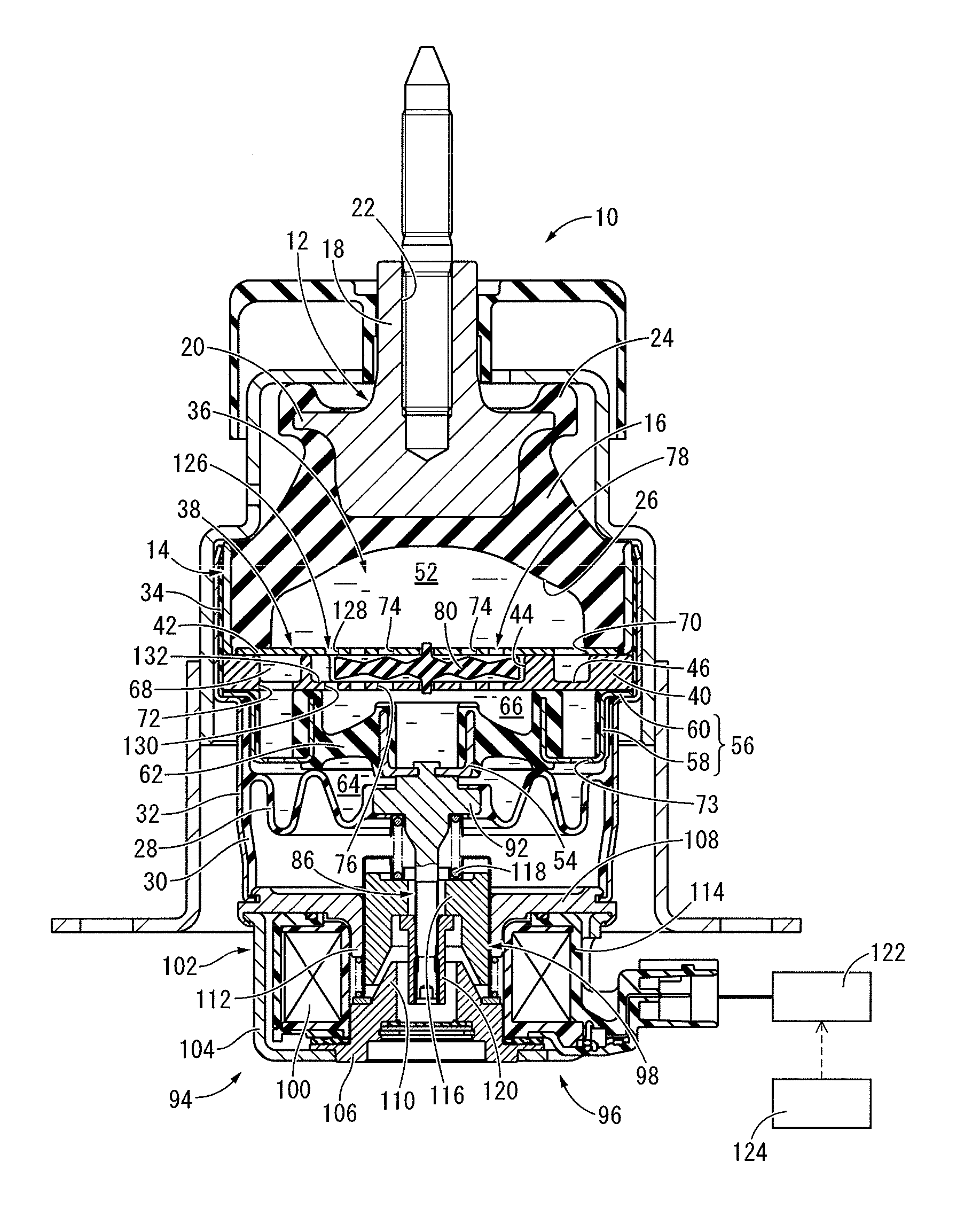
[0028]Referring first to FIG. 1, there is depicted an automotive engine mount 10 according to a first embodiment of a fluid-filled type active vibration damping device constructed in accordance with the present invention. The engine mount 10 has a construction in which a first mounting member 12 and a second mounting member 14 are elastically connected by a main rubber elastic body 16. By the first mounting member 12 being attached to a power unit (not shown) and the second mounting member 14 being attached to a vehicle body (not shown), the engine mount 10 provides vibration damping linkage of the power unit on the vehicle body. In the description hereinbelow, as a general rule, the vertical direction refers to the vertical direction in FIG. 1.

[0029]Described more specifically, first mounting member 12 is a high rigidity component made of a metallic material or the like, and is integrally equipped with a main portion 18 and a flange portion 20. The main portion 18 is of generally s...


PUM


Abstract

A fluid-filled type active vibration damping device including: a pressure-receiving chamber; an equilibrium chamber; an orifice passage permitting fluid flow between the two chambers; an oscillation member oscillated by an electromagnetic actuator; an intermediate chamber; and a pressure transmission passage through which pressure fluctuations produced in the intermediate chamber is applied to the pressure-receiving chamber. The intermediate chamber is provided independently of the equilibrium chamber. The pressure transmission passage comprises a filter orifice tuned to higher frequency than the orifice passage. A movable plate is provided for limiting an amount of fluid flow through the filter orifice. A leak hole is formed for continuously interconnecting the intermediate chamber and the pressure-receiving chamber, and a liquid column resonance frequency of the leak hole is set to not more than half of that of the filter orifice.

Description

INCORPORATED BY REFERENCE[0001]The disclosure of Japanese Patent Application No. 2011-067093 filed on Mar. 25, 2011 including the specification, drawings and abstract is incorporated herein by reference in its entirety.BACKGROUND OF THE INVENTION[0002]1. Field of the Invention[0003]The present invention relates generally to a fluid-filled type vibration damping device that utilizes vibration damping effect on the basis of the flow action of the fluid filling the interior. More particularly, the present invention pertains to a fluid-filled type active vibration damping device capable of exhibiting active vibration damping effect by exerting the oscillation force generated by an electromagnetic actuator on an intermediate chamber.[0004]2. Description of the Related Art[0005]Conventionally, there is known a vibration damping device including: a first mounting member attached to one component of the vibration transmission system; a second mounting member attached to the other component ...

Claims


Application Information

Patent Timeline
IPC IPC(8): F16F13/28F16F13/16
CPCF16F13/268F16F13/105
Inventor KOYAMA, HIRONORIMURAOKA, MUTSUMI
Owner SUMITOMO RIKO CO LTD
Learn More