Lighting control console for controlling a lighting system

a lighting control console and lighting technology, applied in the direction of electrical equipment construction details, lighting and heating apparatus, electric variable regulation, etc., can solve the problem of a larger lighting control consol

Active Publication Date: 2009-06-04
MA LIGHTING TECH
View PDF5 Cites 22 Cited by
  • Summary
  • Abstract
  • Description
  • Claims
  • Application Information

AI Technical Summary

Benefits of technology

[0009]According to an embodiment of the invention, a lighting control console according to the invention can have at least one other control element that gives the user additional control options. The lighting control console can be based on the idea that a cover shields this extra control element, protecting it against external influences. The cover itself can here be adjusted between a closed position and an open position. Only in the closed position of the cover can the extra control element covered to the outside. By contrast, if the cover is in the open position, the user can input operating commands on the extra control element. As a result, then, the cover that can be adjusted between the closed position and the open position can allow the user to use the extra control element at his discretion. Operating commands can only be input with the extra control element in the open position, while external influences and undesired entry of operating commands on the extra control element are precluded with the cover in the closed position. Since the cover can also be used as a supporting surface in its closed position, this yields a particularly compact design while simultaneously allowing the incorporation of a plurality of control elements, since the normally present number of control elements is increased by the extra control elements.
[0010]Another embodiment of the present invention provides a lighting control console for controlling a lighting control system can generate digital actuating commands that can be transmitted via data circuits to the lighting devices of the lighting system. The lighting control console can include at least one digital processor and at least one digital storage unit for generating, managing and storing the actuating commands, a casing that incorporates the digital processor and the digital storage unit, a plurality of control elements that are arranged on the top of the casing and can be used to enter operating commands, and a display device with at least one screen, the display device arranged on the top of the casing, and wherein data for the user can be graphically displayed on the screen. The casing can be provided with at least one cover, which can be adjusted between a closed position and an open position, wherein the cover covers at least one extra control element arranged in or on the casing in its closed position, thereby protecting the extra control element against external influences in its closed position.
[0011]The cover can be structurally adjusted between the closed position and the open position in basically any manner desired. For example, the cover can be pivoted to the casing for this purpose, so that it can swivel between the closed position and the open position. However, it can be advantageous to mount the cover so that it can linearly shift on the casing. For example, this can be structurally realized by attaching linear rails, in particular telescoping rails, between the cover and the casing. The ability of the cover to shift linearly ensures that the orientation of the cover need not be altered while being adjusted between the closed position and the open position, so that the top of the cover in the closed position also forms the top of the cover in the open position. Therefore, given a supporting surface on the top of the cover, said supporting surface can remain available in both the open position and in the closed position.

Problems solved by technology

However, the more control elements are provided on the top of the casing, the larger the lighting control console has to be.

Method used


Image

  • Lighting control console for controlling a lighting system
  • Lighting control console for controlling a lighting system
  • Lighting control console for controlling a lighting system

Examples


Embodiment Construction

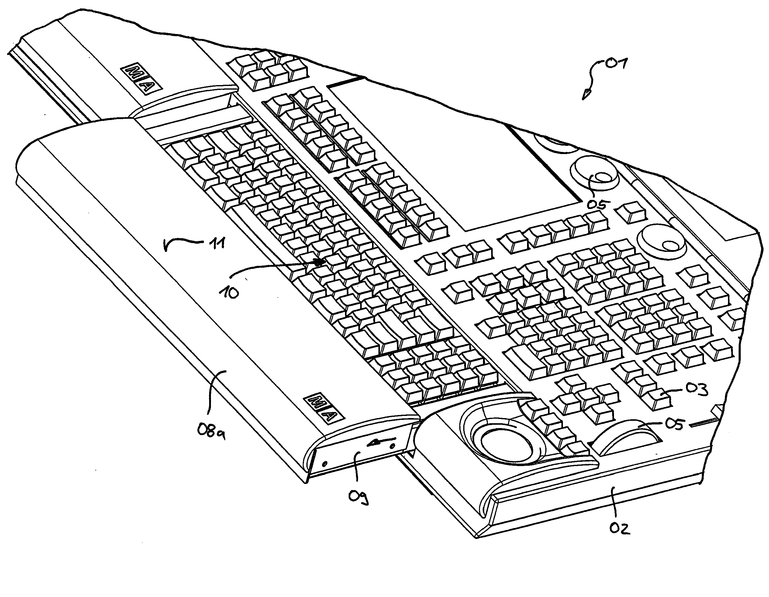
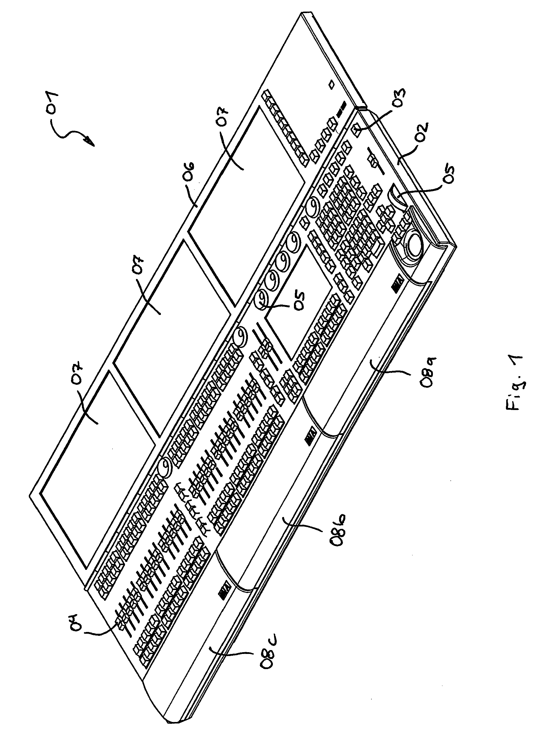
[0029]FIG. 1 shows a lighting control console 01 for controlling a complex lighting system. The casing 02 here incorporates several digital processors and digital storage units for generating, managing and storing digital actuating commands. The top of the casing 02 accommodates a plurality of control elements, specifically keys 03, linear regulators 04 and induction regulators 05. In addition, the lighting control console 01 is equipped with a display device 06 pivoted to the casing 02, which comprises a total of three touch-sensitive touch-screen displays 07.

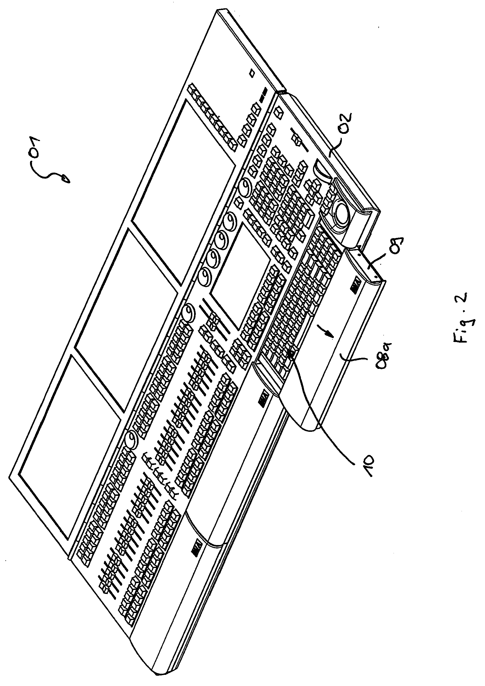
[0030]The lateral edge of the casing 02 facing the user is provided with three covers 08, which each can be adjusted independently from each other between the closed position shown in FIG. 1 and an open position (see FIG. 2).

[0031]FIG. 2 shows the lighting control console 01 after opening the right cover 08a. This is made possible from a structural standpoint by attaching a respective two telescoping rails 09 on the sides of t...


PUM


Abstract

A lighting control console for controlling a lighting control system including a digital processor and a digital storage unit. The lighting control console can comprise several control elements, in particular keys, linear regulators and / or induction regulators, which are arranged on the top of the casing and can be used to enter operating commands. The lighting control console encompasses a display device with at least one screen that is arranged on the top of the casing. The data for the user can be graphically displayed on the screen. The lighting control console can include a casing provided with at least one cover, which can be adjusted between a closed position and an open position, wherein the cover covers at least one extra control element arranged in or on the casing in its closed position, thereby protecting the extra control element against external influences in its closed position.

Description

CROSS REFERENCE TO RELATED APPLICATION[0001]This application claims the priority benefit of German Patent Application No. 10 2007 058 166.3 filed Nov. 30, 2007, the contents of which are hereby incorporated by reference as if fully set forth herein.STATEMENT REGARDING FEDERALLY SPONSORED RESEARCH OR DEVELOPMENT[0002]Not applicable.FIELD OF THE INVENTION[0003]The invention relates to a lighting control console for controlling a lighting system.BACKGROUND OF THE INVENTION[0004]Generic lighting control consoles are used for controlling lighting systems, e.g., of the kind used in theaters or concert stages. These lighting systems routinely encompass a plurality of lighting devices, for example, stage spotlights, wherein the lighting devices can often be switched between a plurality of lighting conditions, e.g., varying colors. Conventional lighting systems can here encompass up to several thousand lighting devices. So that such complex lighting systems can be controlled, the generic lig...

Claims


Application Information

Patent Timeline
Patent Type & Authority Applications(United States)
IPC IPC(8): H05B41/36
CPCH05B37/029H05B47/155
Inventor ADENAU, MICHAEL
Owner MA LIGHTING TECH
Why Eureka
Try Eureka