
Vehicle-use visual field assistance system in which information dispatch apparatus transmits images of blind spots to vehicles

a technology of information dispatch and vehicle, which is applied in the direction of traffic control systems, transportation and packaging, instruments, etc., can solve the problem of difficulty for the driver to directly comprehend the position relationships between objects, and achieve the effect of minimizing the amount of control processing that must be performed by the vehicle-mounted apparatus

Active Publication Date: 2009-06-04
DENSO CORP +1
View PDF10 Cites 108 Cited by
  • Summary
  • Abstract
  • Description
  • Claims
  • Application Information

AI Technical Summary

Benefits of technology

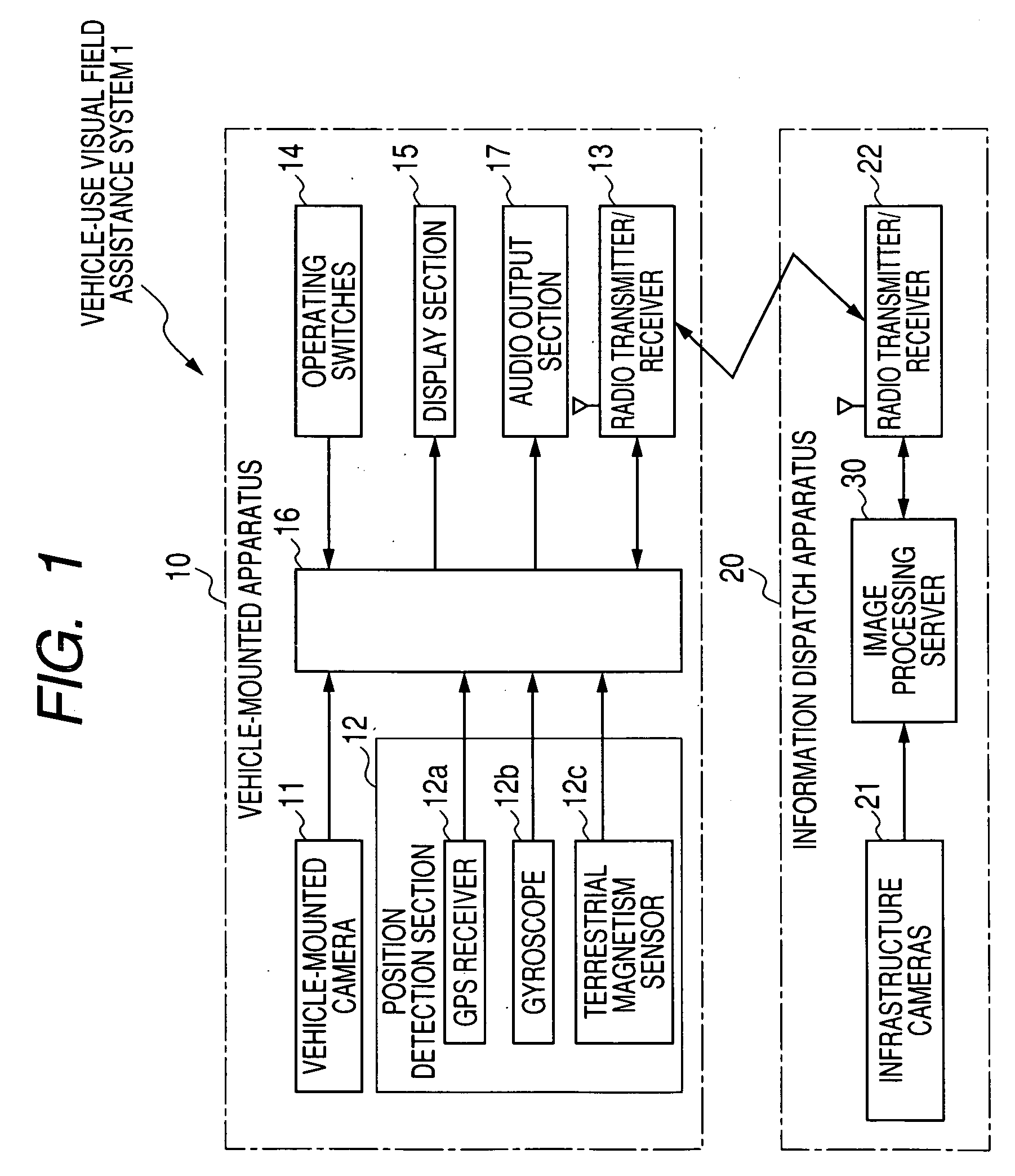
[0010]It is an objective of the present invention to overcome the above problem, by providing a vehicle-use visual field assistance system and information dispatch apparatus which enables the driver of a vehicle to directly ascertain the current conditions within a blind spot that is located in the field of view ahead of the driver, in particular, when the vehicle is approaching a street intersection.

Problems solved by technology

A problem which arises with known types of vehicle-use visual range assistance system such as that described above is that, since the viewpoint of the street intersection camera is substantially different from the viewpoint of the driver of the object vehicle, it is difficult for the driver to directly comprehend the position relationships between the object vehicle and bodies which must be avoided (other vehicles, people, etc.) and which appear in an image that has been captured by the street intersection camera.

Method used


Image

  • Vehicle-use visual field assistance system in which information dispatch apparatus transmits images of blind spots to vehicles
  • Vehicle-use visual field assistance system in which information dispatch apparatus transmits images of blind spots to vehicles
  • Vehicle-use visual field assistance system in which information dispatch apparatus transmits images of blind spots to vehicles

Examples


embodiment 1

Alternative Embodiment 1

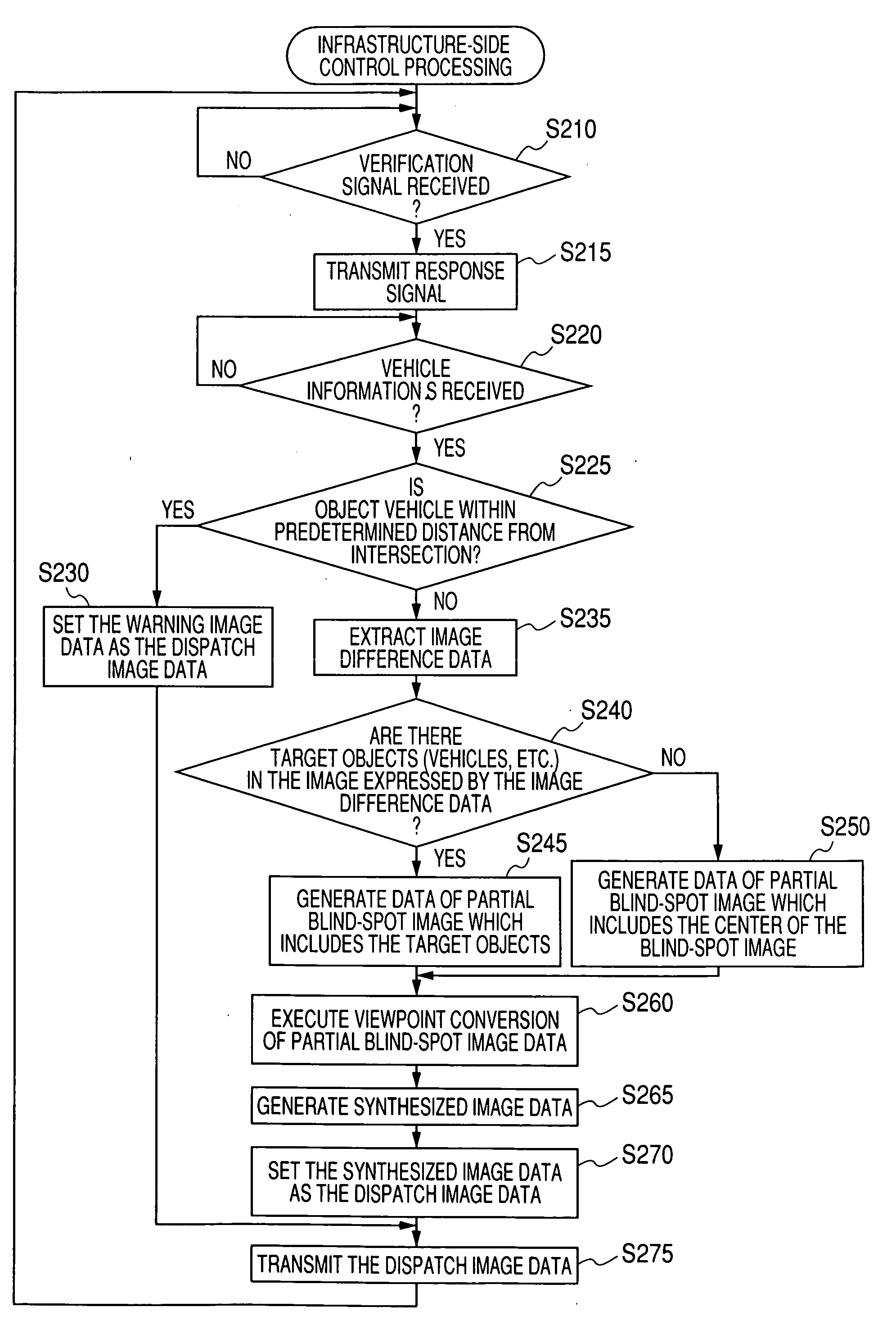
[0112]With the first embodiment described above, the position information SN1 and direction information SN2 of the camera installed on the object vehicle are used as a basis for converting the viewpoint of the partial blind-spot image to the same viewpoint as that of the object vehicle camera. The resultant viewpoint-converted partial blind-spot image data are then combined with the forward-view image data to obtain a synthesized image.

[0113]However it would be equally possible to configure the information dispatch apparatus 20 to convert both the partial blind-spot image data and also the forward-view image data into data expressing an image having the viewpoint of the driver of the object vehicle, and to combine the resultant two sets of viewpoint-converted image data to obtain the synthesized image data. This viewpoint conversion of the forward-view image from the object vehicle camera could be done based upon the relative information SI that is transmitte...

embodiment 2

Alternative Embodiment 2

[0116]Instead of using an extracted section of a blind-spot image to generate a partial blind-spot image as described for the first embodiment above, it would be equally possible to perform viewpoint conversion of the difference image (expressed by the image difference data extracted in step S235 of FIG. 5) and to combine the resultant viewpoint-converted image difference data with the forward-view image data to obtain a synthesized image. In that case, the synthesized image would show only those target objects (vehicles, people) that are currently within the blind spot, combined with the forward-view image. Other (background) components of the blind-spot image would not appear in the synthesized image.

[0117]In that case, when performing synthesis of the image data, image enhancement processing (e.g., contrast enhancement, color enhancement, etc.) could be applied to the image difference data, to render the target bodies (vehicles, people) in the blind spot m...

embodiment 3

Alternative Embodiment 3

[0118]Instead of using partial blind-spot image data as with the above embodiment, it would be possible to perform viewpoint conversion of the data of an entire blind-spot image, and combine the resultant viewpoint-converted blind spot image data with the forward-view image data to obtain the synthesized image.


PUM


Abstract

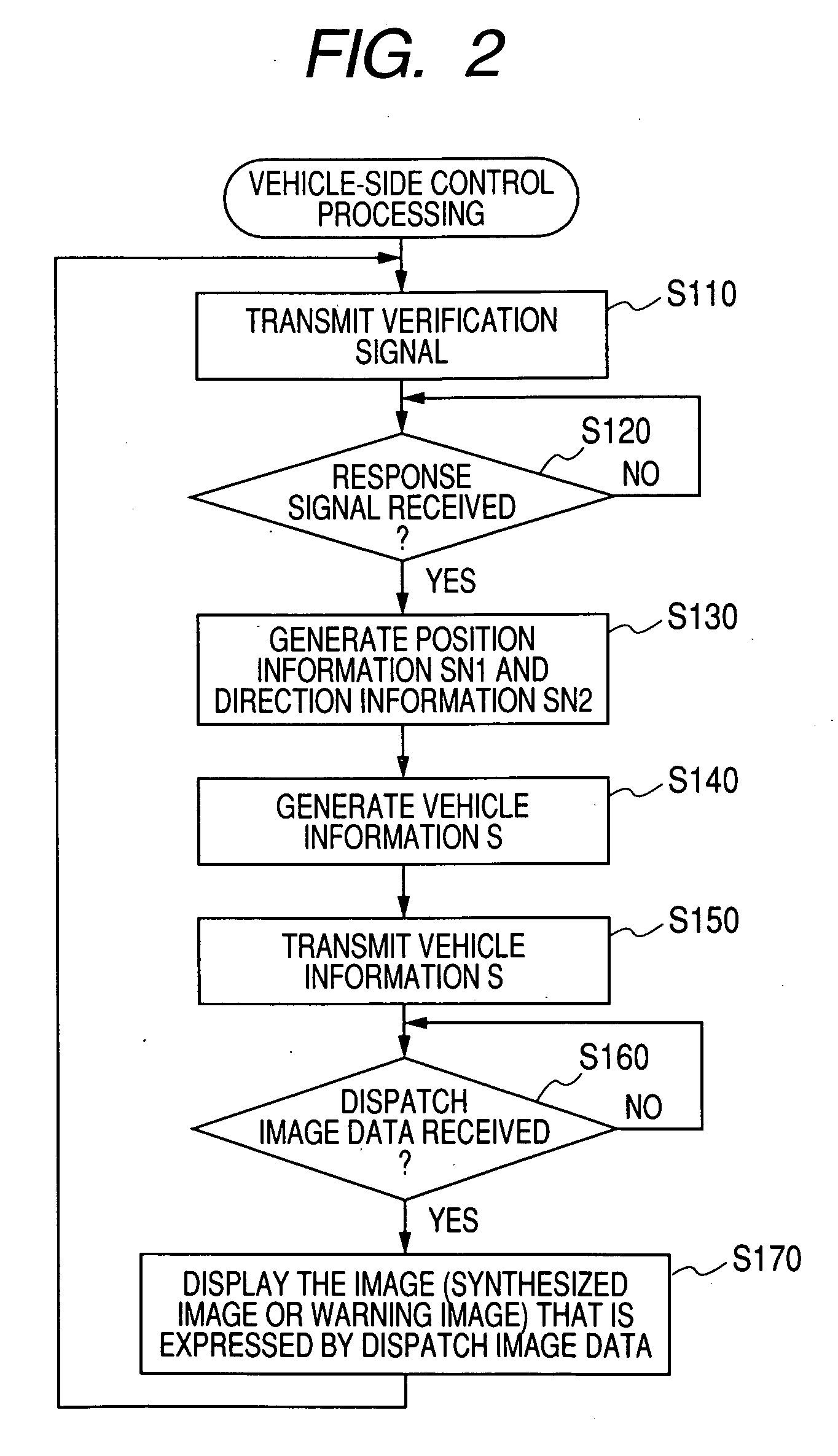
A camera of a ground-based information dispatch apparatus captures a blind-spot image, showing a region that is a blind spot with respect to a vehicle driver. A vehicle-mounted camera captures a forward-view image corresponding to the viewpoint of the driver, and the forward-view image is transmitted to the information dispatch apparatus together with vehicle position and direction information and camera parameters. Based on the received information, the blind-spot image is converted to a corresponding image having the viewpoint of the vehicle driver, and the forward-view image and viewpoint-converted blind-spot image are combined to form a synthesized image, which is transmitted to the vehicle.

Description

CROSS-REFERENCE TO RELATED APPLICATIONS[0001]This application is based on and incorporates herein by reference Japanese Patent Application No. 2007-239494 filed on Sep. 14, 2007.BACKGROUND OF THE INVENTION[0002]1. Field of Application[0003]The present invention relates to a vehicle-use visual field assistance system incorporating an information dispatch apparatus, for providing assistance to the driver of a vehicle by transmitting images to the vehicle showing conditions within regions (blind spots) which are blocked from the field of view of the driver by external objects such as buildings.[0004]2. Description of Related Art[0005]Types of vehicle-use visual field assistance system are known whereby when a vehicle (referred to in the following as the object vehicle) approaches the vicinity of a street intersection where the view ahead of the vehicle is partially obstructed by bodies external to the vehicle, such as buildings located at the right and / or left sides of the intersection...

Claims


Application Information

Patent Timeline
Patent Type & Authority Applications(United States)
IPC IPC(8): G08G1/123B60Q1/00G08G1/00
CPCG08G1/164B60R1/00
Inventor SAKAI, HIROSHITAMATSU, YUKIMASADATTA, ANKURSHEIKH, YASERKANADE, TAKEO
Owner DENSO CORP
Learn More