Radar apparatus and mounting structure for radar apparatus

a technology for mounting structures and radars, which is applied in the direction of antennas, instruments, antenna details, etc., can solve the problems of unstable obstacle detection capability of radar apparatuses, damage to radar apparatuses by bumpers, and unstable characteristic of reflected radar waves of radar apparatuses

Active Publication Date: 2009-06-04
DENSO CORP
View PDF11 Cites 13 Cited by
  • Summary
  • Abstract
  • Description
  • Claims
  • Application Information

AI Technical Summary

Benefits of technology

[0015]According to the present invention, since it is possible to prevent the radar wave transmitted from a radar apparatus covered by a cover member from being repeatedly reflected between the radar apparatus and the cover member, the object (obstacle) detection performance of the radar apparatus can be stabilized in the case where the radar apparatus is covered by the cover member on the side of a transmission direction of the radar wave.

Problems solved by technology

However, when a radar apparatus is mounted on the inner surface of a bumper, there is possibility that the radar apparatus is damaged by the bumper when the bumper vibrates even slightly, or when the bumper is hit by a stone or the like.
However, in this case, since a transmitted radar wave is repeatedly reflected between the bumper and the surface of an antenna device of the radar apparatus, the detection characteristic of the reflected radar wave of the radar apparatus may become unstable, and accordingly, the obstacle detecting capability of the radar apparatus may be unstable.

Method used


Image

  • Radar apparatus and mounting structure for radar apparatus
  • Radar apparatus and mounting structure for radar apparatus
  • Radar apparatus and mounting structure for radar apparatus

Examples


Embodiment Construction

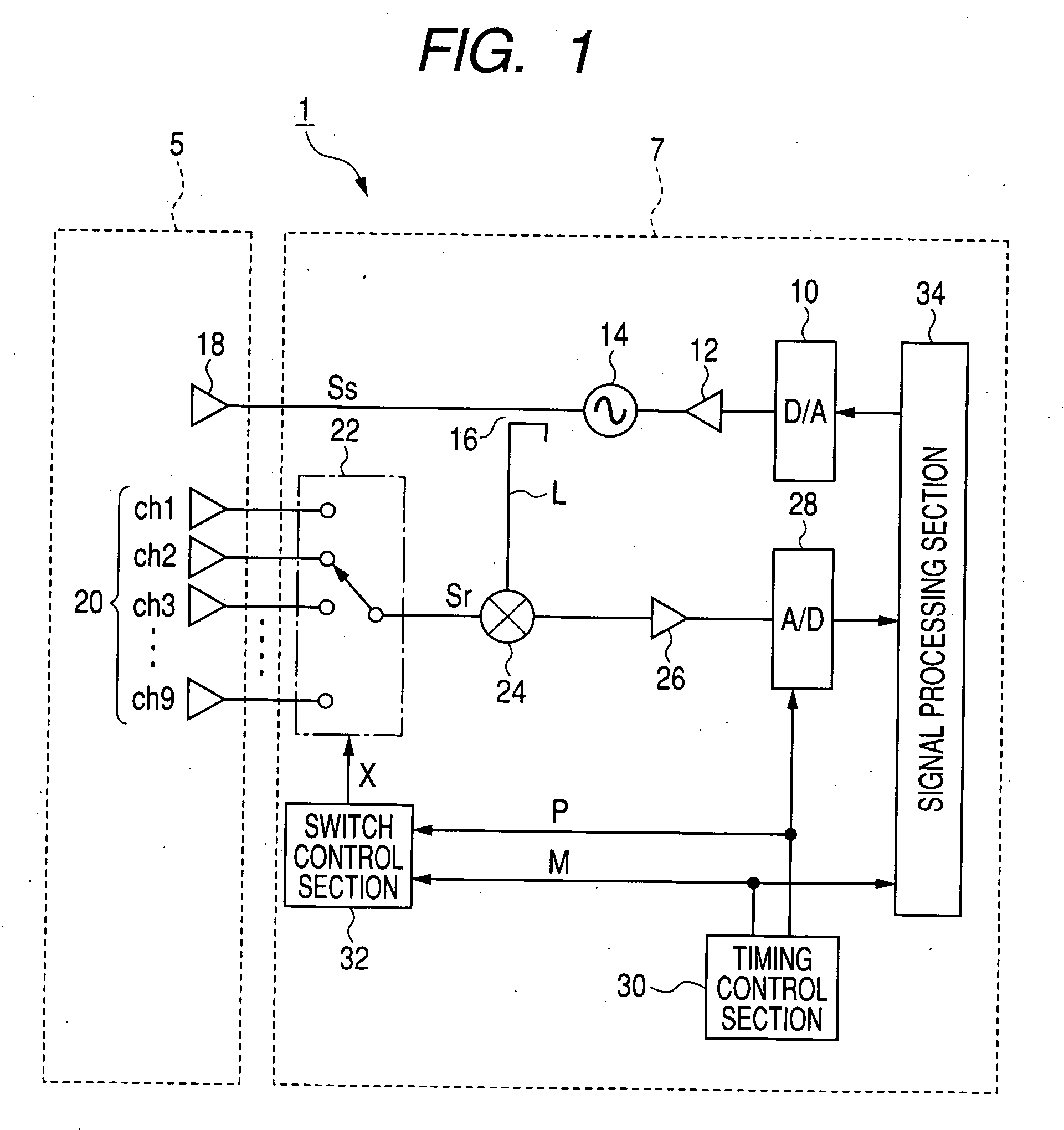
[0026]FIG. 1 is a block diagram showing an overall structure of a vehicle-mounted radar apparatus according to an embodiment of the invention. As shown in FIG. 1, the radar apparatus 1 includes a D / A converter 10, a VCO (Voltage Controlled Oscillator) 14, a distributor 16, and a transmitting antenna 18. The D / A converter 10 generates an FMCW modulation signal having a triangular waveform in accordance with a modulation command. The VCO 14, which is applied with the modulation signal generated by the D / A converter 10 through a buffer 12, generates an output whose frequency varies depending on the modulation signal. The distributor 16 splits the output of the VCO 14 into a transmit signal Ss and a local signal L. The transmitting antenna 18 emits a radar wave in accordance with the transmit signal Ss.

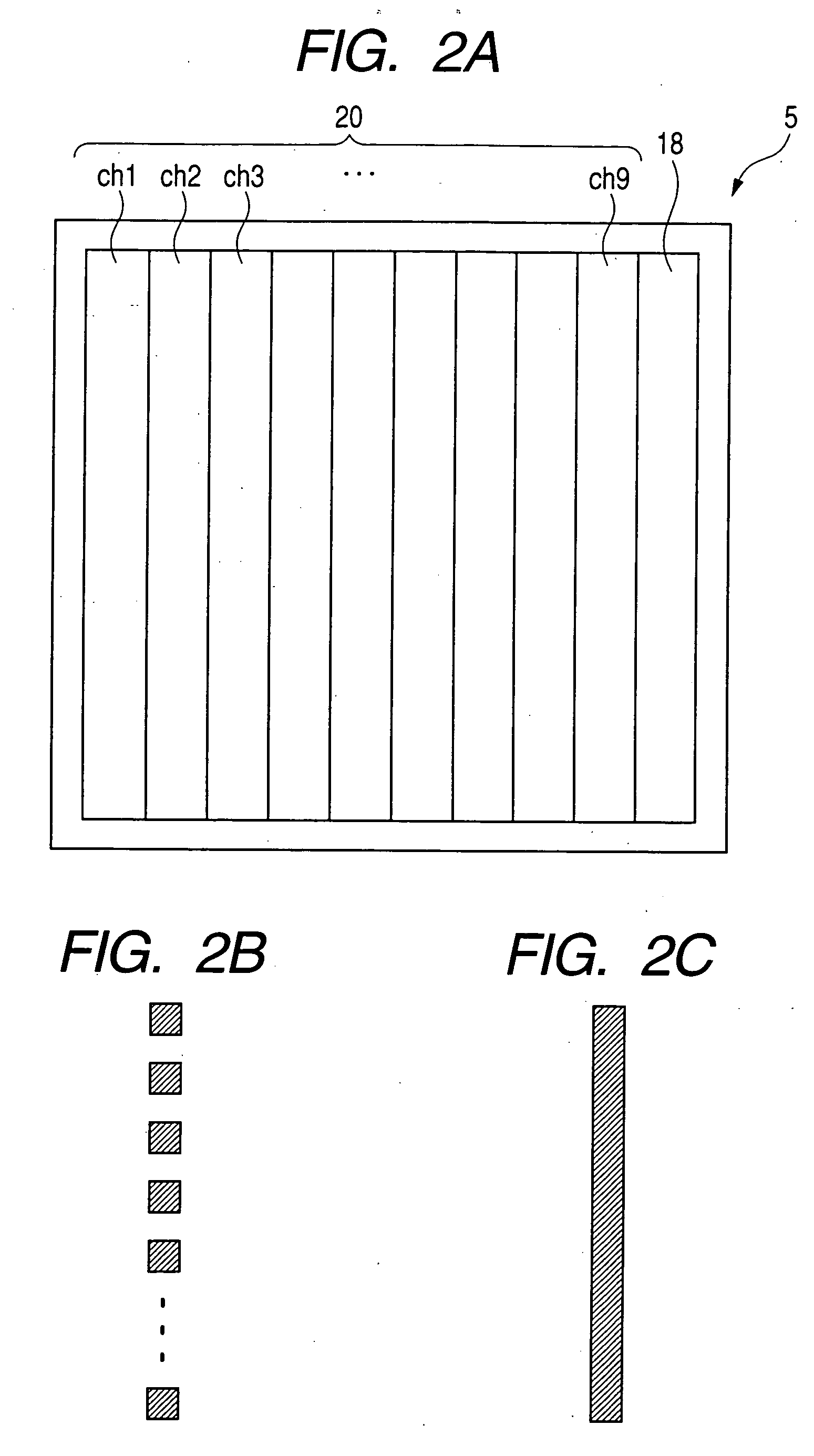
[0027]The radar apparatus 1 further includes a receiving antenna 20 constituted by 9 element antennas for receiving the reflected radar wave, a receiver switch 22, a mixer 24, an amplifie...


PUM


Abstract

The radar apparatus includes an antenna device including a transmitting antenna and a receiving antenna, a main body which generates a radar wave, transmits the radar wave from the transmitting antenna, and receives the radar wave reflected from an obstacle to be detected by the receiving antenna, and a cover member covering the main body and the antenna device on a side of a transmission direction of the radar wave and located out of contact with the main body and the antenna device. The cover member has a transmission portion allowing the radar wave to pass therethrough, a surface of the transmission portion facing the antenna device being inclined by an angle greater than 3 degrees with respect to an antenna surface of the receiving antenna.

Description

CROSS-REFERENCE TO RELATED APPLICATION[0001]This application is related to Japanese Patent Application No. 2007-272709 filed on Oct. 19, 2007, the contents of which are hereby incorporated by reference.BACKGROUND OF THE INVENTION[0002]1. Field of the Invention[0003]The present invention relates to a radar apparatus, and a mounting structure for the radar apparatus.[0004]2. Description of Related Art[0005]As described, for example, in Japanese Patent Application Laid-open No. 2003-240838, it is known to mount a radar apparatus on the inner surface of a bumper of a vehicle so as to be covered by the bumper as a cover member.[0006]However, when a radar apparatus is mounted on the inner surface of a bumper, there is possibility that the radar apparatus is damaged by the bumper when the bumper vibrates even slightly, or when the bumper is hit by a stone or the like.[0007]It may occur that the radar apparatus is mounted not on the inner surface of the bumper, but fixed to a certain member...

Claims


Application Information

Patent Timeline
Patent Type & Authority Applications(United States)
IPC IPC(8): G01S7/03G01S13/93G01S13/931
CPCG01S7/034G01S13/931G01S2013/9375H01Q1/3233H01Q3/40G01S2013/9389G01S2013/93271G01S2013/93275
Inventor KATO, YUSUKEFUJITA, AKIHISAAOKI, YUTAKA
Owner DENSO CORP
Why Eureka
Try Eureka