Eureka AIR delivers breakthrough ideas for toughest innovation challenges, trusted by R&D personnel around the world.

Recording Device and Recording Medium Conveying Method

Active Publication Date: 2009-06-04
BROTHER KOGYO KK
View PDF0 Cites 2 Cited by
  • Summary
  • Abstract
  • Description
  • Claims
  • Application Information

AI Technical Summary

Benefits of technology

[0007]Certain illustrative aspects of the present invention provide a recording device and a recording medium conveying method which do not require a mechanism for moving a reading member and thus simplify a configuration of the device. According to an aspect of the present invention, a recording device may comprise a conveying member having a through hole, the conveying member conveying a recording medium, which is placed on a first surface of the conveying member on a front side. The recording device may further comprise a reading member arranged to face the first surface of the conveying member, the reading member reading an image on the first surface or an image on the recording medium on the first surface. The recording device may also comprise a cleaning member arranged to face a second surface of the conveying member on a back side, at a position facing the reading member with the conveying member interposed therebetween, the cleaning member cleaning the reading member.

Problems solved by technology

Thus, the configuration of the device may be complicated.

Method used


Image

  • Recording Device and Recording Medium Conveying Method
  • Recording Device and Recording Medium Conveying Method
  • Recording Device and Recording Medium Conveying Method

Examples


Embodiment Construction

[0015]An illustrative embodiment of the present invention, and their features and advantages, may be understood with reference to the attached drawings, like numerals being used for corresponding parts in the various drawings.

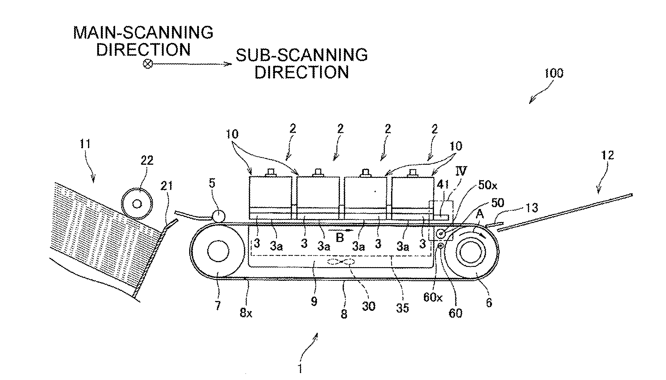
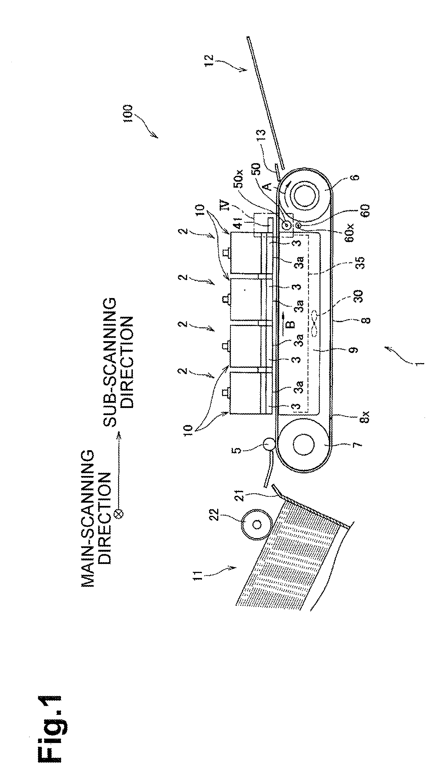
[0016]Referring to FIG. 1, the inkjet printer 100 may be a color inkjet printer comprising a plurality of, e.g., four, inkjet heads 2 which respectively eject ink of magenta, cyan, yellow, and black.

[0017]The plurality of inkjet heads 2 may extend in a main-scanning direction (i.e., direction orthogonal to a sheet plane of FIG. 1), and may be arranged in a sub-scanning direction (i.e., direction being orthogonal to the main-scanning direction and extending along a conveying direction B). The plurality of inkjet heads 2 may be supported by a printer body via a frame. The inkjet printer 100 may be a line printer having an ejection region extending in the main-scanning direction.

[0018]Each inkjet head 2 may include a head body 3 arranged at a lower end, and a rese...


PUM


Abstract

A cleaning roller is arranged at a position facing an image sensor with a conveying belt interposed therebetween. The conveying belt has a through hole. In an image sensor cleaning mode, the cleaning roller is inserted through the through hole and contacts the image sensor, while the image sensor is held without moving.

Description

CROSS REFERENCE TO RELATED APPLICATION[0001]This application claims priority from Japanese Patent Application No. 2007-309894, filed Nov. 30, 2007, the entire subject matter of which is incorporated herein by reference.BACKGROUND[0002]1. Field[0003]Aspects of the present invention relate to a recording device and a recording medium conveying method.[0004]2. Description of the Related Art[0005]A known recording device conveys a sheet as a recording medium, and records an image on the sheet by ejecting ink from a plurality of nozzles. The recording device checks ejection of ink from nozzles. In the recording device, a chart is printed on a conveying belt, and a reading portion arranged adjacent to a head reads the chart, so as to detect an ink-ejection failure of nozzles. Herein, the reading member is sealed to prevent foreign substances floating in the device, such as ink mist or paper dust, from adhering to the reading member. Also, the reading member is cleaned to prevent an errone...

Claims


Application Information

Patent Timeline
IPC IPC(8): B41J2/165
CPCB41J2/16585
Inventor YAMAMOTO, HIDEKI
Owner BROTHER KOGYO KK
Why Eureka
Eureka Blog
Learn More