
Ink cartridges and ink supply systems

a technology of ink supply system and cartridge, which is applied in printing and other directions, can solve the problems of ink leakage from the ink supply opening, and user difficulty in mounting the ink cartridge to the cartridge mounting portion,

Active Publication Date: 2009-06-04
BROTHER KOGYO KK
View PDF2 Cites 45 Cited by
  • Summary
  • Abstract
  • Description
  • Claims
  • Application Information

AI Technical Summary

Benefits of technology

[0011]Therefore, a need has arisen for ink cartridges and ink supply systems which overcome these and other shortcomings of the related art. A technical advantage of the invention is that ink leakage is suppressed. Another technical advantage of the invention is that an ink cartridge is easily mounted to a cartridge mounting portion.
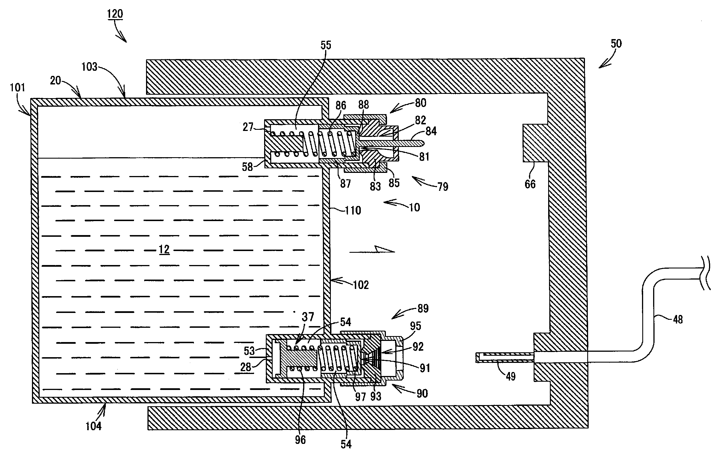
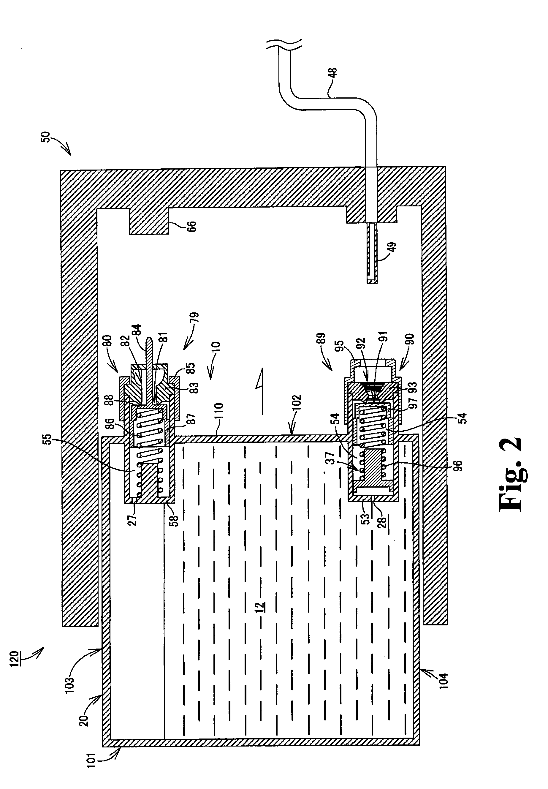
[0012]According to an embodiment of the invention, an ink cartridge comprises a case comprising an ink chamber configured to store ink therein and a particular wall. The ink cartridge also comprises an air communication portion positioned at the particular wall and having a first opening formed therethrough, wherein the air communication portion is configured to place an interior of the ink chamber and an exterior of the ink chamber in fluid communication via the first opening. The air communication portion comprises a first lid member configured to move between a first position and a second position, wherein when the first lid member is in the first position, the first lid member does not cover the first opening and when the first lid member is in the second position, the first lid member covers the first opening, and a first biasing member configured to apply a first biasing force to the first lid member toward the first opening. The ink cartridge also comprises an ink supply portion positioned at the particular wall and having a second opening formed therethrough, wherein the ink supply portion is configured to supply ink from the interior of the ink chamber to the exterior of the ink chamber via the second opening. The ink supply portion comprises a second lid member configured to move between a third position and a fourth position, wherein when the second lid member is in the third position, the second lid member does not cover the second opening and when the second lid member is in the fourth position, the second lid member covers the second opening, and a second biasing member configured to apply a second biasing force to the second lid member toward the second opening, wherein when the first lid member is in the second position and the second lid member is in the fourth position, the first biasing force is less than the second biasing force.
[0013]According to another embodiment of the invention, an ink supply system comprises a cartridge mounting portion, and an ink cartridge configured to be mounted to the cartridge mounting portion. The ink cartridge comprises a case comprising an ink chamber configured to store ink therein and a particular wall. The ink cartridge also comprises an air communication portion positioned at the particular wall and having a first opening formed therethrough, wherein the air communication portion is configured to place an interior of the ink chamber and an exterior of the ink chamber in fluid communication via the first opening. The air communication portion comprises a first lid member configured to move between a first position and a second position, wherein when the first lid member is in the first position, the first lid member does not cover the first opening and when the first lid member is in the second position, the first lid member covers the first opening; and a first biasing member configured to apply a first biasing force to the first lid member toward the first opening. The ink cartridge also comprises an ink supply portion positioned at the particular wall and having a second opening formed therethrough, wherein the ink supply portion is configured to supply ink from the interior of the ink chamber to the exterior of the ink chamber via the second opening. The ink supply portion comprises a second lid member configured to move between a third position and a fourth position, wherein when the second lid member is in the third position, the second lid member does not cover the second opening and when the second lid member is in the fourth position, the second lid member covers the second opening, and a second biasing member configured to apply a second biasing force to the second lid member toward the second opening. When the ink cartridge is mounted to the cartridge mounting portion, the ink supply portion is positioned below the air communication portion, the first lid member is in the first position, the second lid member is in the third position, and the first biasing force is greater than the second biasing force.

Problems solved by technology

Therefore, when the ink cartridge is mounted to the cartridge mounting portion, the side face of the case extends in the gravitational direction, such that the ink supply opening is positioned at the lowermost position with respect to the surface of ink stored in the ink chamber, and hence ink may leak via the ink supply opening.
When the first biasing force and the second biasing force are set to be relatively weak, a user may easily mount the ink cartridge to the cartridge mounting portion because a force which the user receives from the resilient members are relatively weak.
Nevertheless, ink may leak from the ink supply opening because the supply valve may not cover the ink supply opening reliably.
Nevertheless, the user may have a difficulty in mounting the ink cartridge to the cartridge mounting portion because the user receives a relatively strong force from the resilient members.
If different resilient members are used for biasing the supply valve and biasing the air valve, an operator may improperly install the incorrect resilient members when the ink cartridge is manufactured.
The assembly work of the ink cartridge may become complicated.

Method used


Image

  • Ink cartridges and ink supply systems
  • Ink cartridges and ink supply systems
  • Ink cartridges and ink supply systems

Examples


case 20

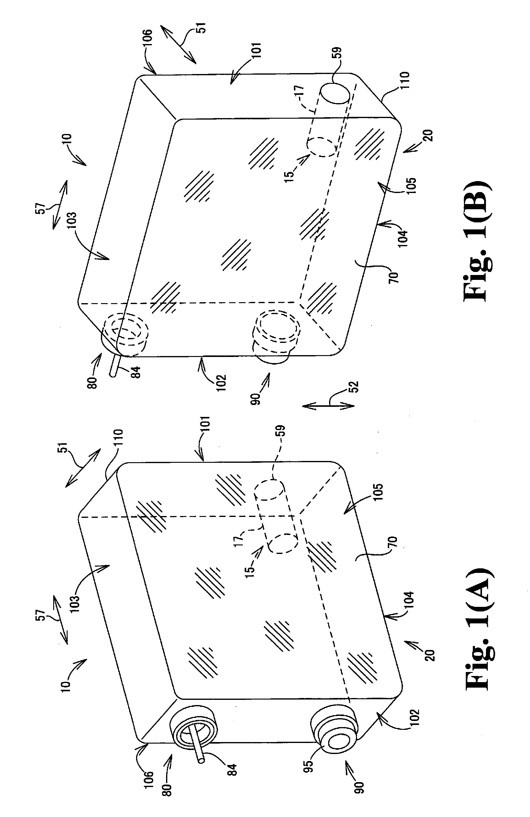
[0030]Case 20 may comprise a front wall 102, a rear wall 101 positioned opposite front wall 102, a top wall 103 extending between front wall 102 and rear wall 101, a bottom wall 104 extending between front wall 102 and rear wall 101 and positioned opposite top wall 103, a left wall 105 extending between front wall 102 and rear wall 101, and a right wall 106 extending between front wall 102 and rear wall 101 and positioned opposite left wall 105. Each of front wall 102, rear wall 101, top wall 103, bottom wall 104, left wall 105, and right wall 106 may face the exterior of case 20, and define the outer appearance of case 20. When cartridge 10 is inserted into cartridge mounting portion 50, case 20 may be inserted from a front wall 102 side.

[0031]When ink cartridge 10 is mounted to cartridge mounting portion 50, top wall 103 is positioned at the top of case 20 and bottom wall 104 is positioned at the bottom of case 20. Each of an area of left wall 105 and an area of right wall 106 may...


PUM


Abstract

An ink cartridge includes a case having an ink chamber and a wall, an air communication portion having a first opening, and an ink supply portion having a second opening. The air communication portion includes a first lid member that moves between a first position not covering the first opening, and a second position covering the first opening, and a first biasing member that applies a first biasing force to the first lid member. The ink supply portion includes a second lid member that moves between a third position not covering the second opening and a fourth position covering the second opening, and a second biasing member that applies a second biasing force to the second lid member. When the first lid member is in the second position and the second lid member is in the fourth position, the first biasing force is less than the second biasing force.

Description

CROSS-REFERENCE TO RELATED APPLICATION[0001]The present application claims priority from Japanese Patent Application No. JP-2007-311821, which was filed on Dec. 1, 2007, the disclosure of which is incorporated herein by reference in its entirety.BACKGROUND OF THE INVENTION[0002]1. Field of the Invention[0003]The invention relates to ink cartridges and ink supply systems.[0004]2. Description of Related Art[0005]A known ink-jet image recording apparatus has a recording head and an ink supply system configured to supply ink to the recording head. The known ink supply system has a known cartridge mounting portion, and a known ink cartridge is configured to be mounted to the cartridge mounting portion. The known ink cartridge has a case, and the case has an ink chamber formed therein. The ink chamber is configured to store ink therein. The known ink cartridge has an ink supply portion, and ink is supplied from an interior of the ink chamber to an exterior of the ink chamber via the ink s...

Claims


Application Information

Patent Timeline
Patent Type & Authority Applications(United States)
IPC IPC(8): B41J2/175
CPCB41J2/17513B41J2/17523B41J2/1752
Inventor TAKAGI, YUKI
Owner BROTHER KOGYO KK
Learn More