
Tibial Aiming Device For The Double Channel Technique

a double channel technique and aiming device technology, applied in the field of aiming devices for the double channel technique, can solve the problems of difficult to target this point from the outside, limited vision of surgeons, and tearing of the front cruciate ligament, and achieve the effect of considerably facilitating handling

Inactive Publication Date: 2009-06-04
KARL STORZ GMBH & CO KG
View PDF10 Cites 118 Cited by
  • Summary
  • Abstract
  • Description
  • Claims
  • Application Information

AI Technical Summary

Benefits of technology

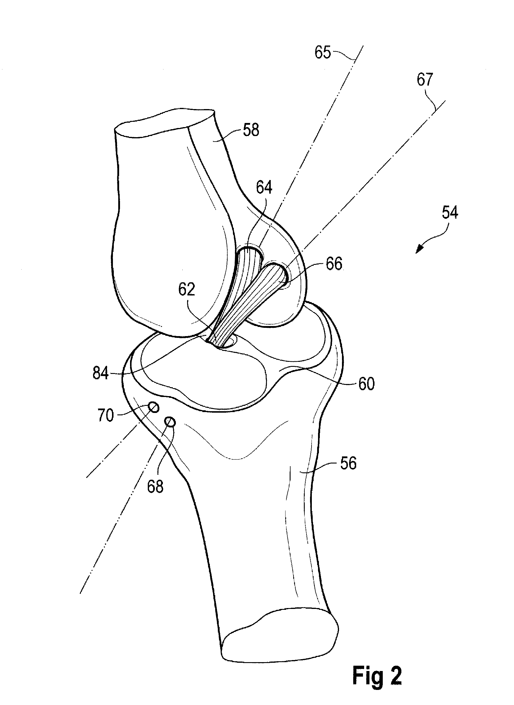
[0026]By selecting the distance between the first opening and the second opening, the position and divergence corresponding to the position and divergence of both bundles of the front cruciate ligament can be preset. From here on a second target wire is pushed through the guide sleeve and the bone until it likewise exits on the tibial plateau, though slightly offset medially to the already set first target wire. Since the middle longitudinal axis of the guide sleeve is in alignment with the first opening, the procedure ensures that both target wires do not hinder or contact one another. This secure guiding, the orientation and alignment are also guaranteed by the first target wire being housed in the second opening when the second target wire is set, thus having a preset orientation to the second target wire.
[0041]Handling therefore becomes easier still by the openings being designed as continuous openings. In particular, in connection with the abovementioned step, according to which the first opening is still open to the side, handling is made considerably easier.

Problems solved by technology

In particular, the front cruciate ligament is subject to very high stresses which can result in the front cruciate ligament tearing.
During arthroscopy the surgeon has available a relatively restricted field of vision and also only relatively little space in the knee joint for manipulation.
The exit point of the bore channel introduced from the outside of the tibia, which lies on the tibial plateau, is thus barely seen, such that it is very difficult to target this point from the outside.

Method used


Image

  • Tibial Aiming Device For The Double Channel Technique
  • Tibial Aiming Device For The Double Channel Technique
  • Tibial Aiming Device For The Double Channel Technique

Examples


Embodiment Construction

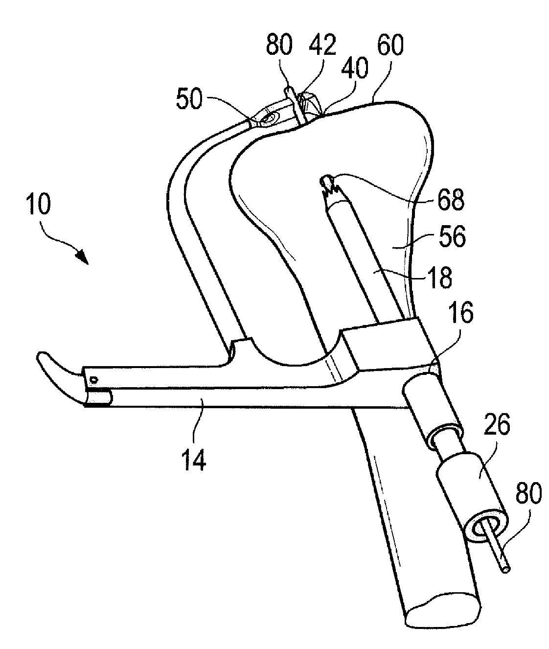
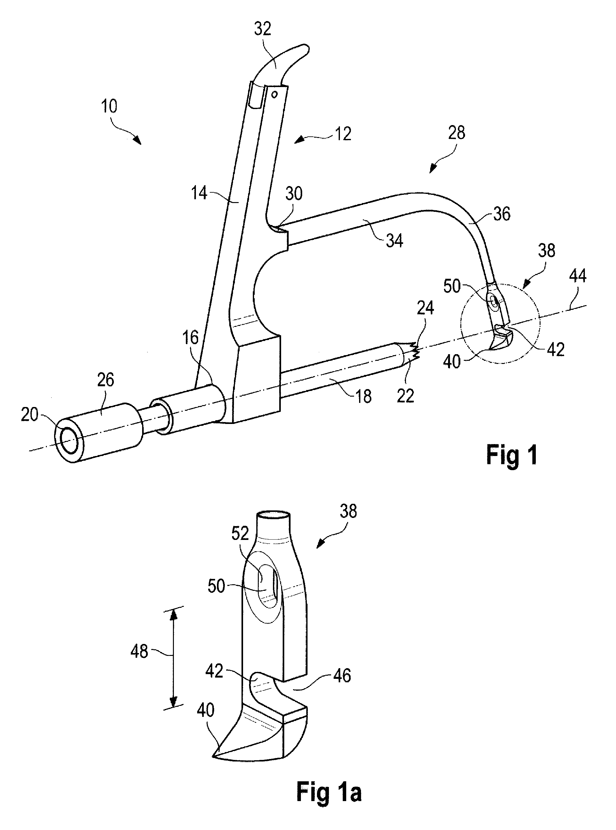
[0052]A device illustrated in FIG. 1 or 1a is designated in its entirety by reference numeral 10.

[0053]The device 10 has a handle 12 which has a straight, long stretched-out rod-like grip 14. A guide sleeve 18 is inserted in an opening 16 at an end region. The guide sleeve 18 has a tube 20 whereof the distal end 22 is fitted with a notched crown24. At the opposite end the guide sleeve 18 is provided with a clamping sleeve 26. The clamping mechanism is designed such that turning the clamping sleeve 26 in one direction produces localized retaining of the guide sleeve 18, for example in the alignment or shift position illustrated in FIG. 1.

[0054]If the clamping sleeve 26 is rotated in the opposite direction the guide sleeve 18 can be moved reciprocally along its longitudinal axis 44, or can also be completely removed from the grip 14, to the left in the illustration of FIG. 1.

[0055]An arm 28 protrudes from the rod-like grip 14, viewed approximately at half height. The arm 28 is housed ...


PUM


Abstract

A device (10) serves to target and introduce bore channels into a tibia in the vicinity of a knee joint during reconstruction of the front cruciate ligament. It has a handle (12), a guide sleeve (18) removably attached to said handle, said guide sleeve having a longitudinal axis (44). A distal end of said guide sleeve (18) constitutes a first aiming point. An arm (28) protrudes from said handle (12). A distal end of said arm constitutes a second aiming point. A first opening (42) is provided in a distal end region of said arm, said opening (42) being in alignment with said longitudinal axis (44). A second opening (50) is provided in that distal end region of said arm, said second opening (50) is at a distance from said first opening (42).

Description

BACKGROUND OF THE INVENTION[0001]The invention relates to a device for targeting and introducing bore channels into the tibia in the vicinity of the knee joint during reconstruction of a front cruciate ligament.[0002]Such a tibial aiming device for the front cruciate ligament is known from the catalogue “Arthroscopy, Sports Medicine, Spinal Surgery, 2nd edition January / 2005, page 71” by Karl Storz GmbH & Co. KG, Tuttlingen, Germany.[0003]This device has a handle, with a guide sleeve attached removably on the handle, the distal end of which constitutes a first aiming point on the bone, with a protruding arm, whereof the distal end constitutes a second aiming point on the tibial plateau, whereby in the region of its distal end the arm has a first opening which is in alignment with a longitudinal axis of the guide sleeve such that a target wire guided through the guide sleeve encounters the first opening after penetrating the bone when the device is placed on the tibia.[0004]The front ...

Claims


Application Information

Patent Timeline
Patent Type & Authority Applications(United States)
IPC IPC(8): A61B17/58
CPCA61B17/1764A61B17/1714
Inventor PETERSEN, WOLFZANTOP, THOREBERBERICH, SASCHASAUER, MICHAELSUMMERER, SABINE
Owner KARL STORZ GMBH & CO KG
Learn More