
Dilation and Stent Delivery System for Bifurcation Lesions

a stent and bifurcation technology, applied in the field of vascular disease treatment, can solve the problems of ostium collapse, cumbersome process, and cumbersome conventional balloon angioplasty, and achieve the effect of efficient and accurate stent deployment and dilatation of bifurcation lesions

Inactive Publication Date: 2009-06-04
BOSTON SCI SCIMED INC
View PDF61 Cites 21 Cited by
  • Summary
  • Abstract
  • Description
  • Claims
  • Application Information

AI Technical Summary

Benefits of technology

The present invention is a device that can be used to treat blockages in the blood vessels. It can track over two guidewires, which are placed in each branch vessel of a bifurcation. This device allows for efficient and accurate placement of stents and dilation of bifurcation lesions.

Problems solved by technology

In either case, restriction of the vessel caused by the stenotic lesion results in many well known problems caused by the reduction or cessation of blood circulation through the restricted vessel.
However, when the lesion is formed in a bifurcation, conventional balloon angioplasty can be somewhat cumbersome.
Not only is this process somewhat cumbersome, other problems result as well.
For example, when the angle between the branch vessels in the bifurcation is fairly small, inflation of the dilatation balloon in one branch vessel can cause the ostium of the other branch vessel to collapse.
This results in ineffective dilatation by restricting flow to the other branch vessel.
Further, locating both branch vessels can be quite difficult.
This can be somewhat cumbersome.
While there have recently been considerable advances in stent design and stent deployment techniques, there is currently no adequate method of treating bifurcation lesions, particularly where both downstream branch vessels are affected by the lesion.
However, this compromises the ostium of the unstented branch.
This presents significant difficulties.
For example, dilating between the struts of the stent already deployed tends to distort that stent.
Further, deploying the second stent through the struts of the first stent is not only difficult, but it can also distort the first stent.

Method used


Image

  • Dilation and Stent Delivery System for Bifurcation Lesions
  • Dilation and Stent Delivery System for Bifurcation Lesions
  • Dilation and Stent Delivery System for Bifurcation Lesions

Examples


Embodiment Construction

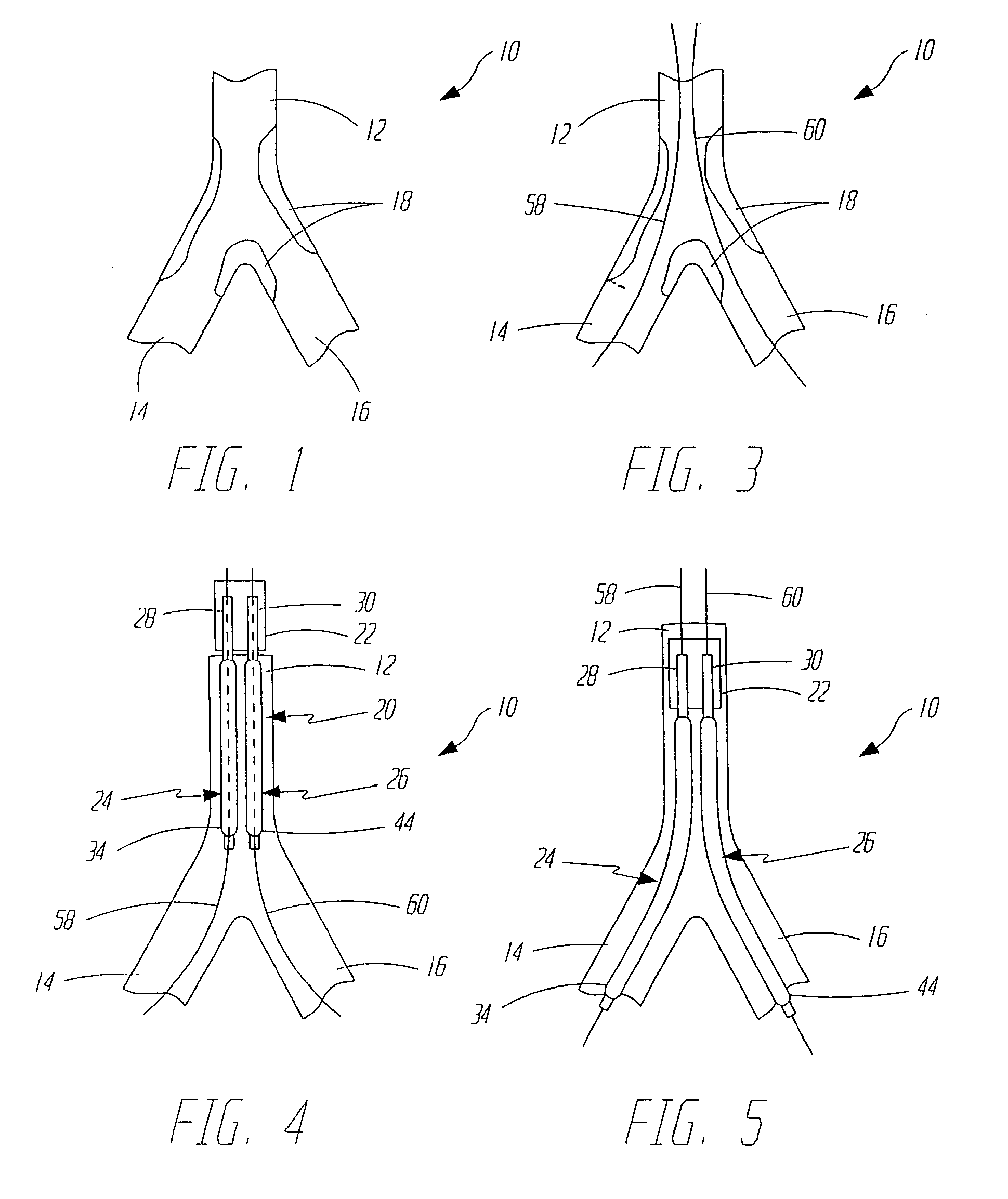
[0026]FIG. 1 illustrates a bifurcation 10 which includes parent vessel 12, first branch vessel 14 and second branch vessel 16. FIG. 1 also illustrates that a bifurcation lesion 18 has developed in bifurcation 10. Lesion 18 illustrates one common bifurcation lesion in that it extends up into parent vessel 12 and down into both branch vessels 14 and 16.

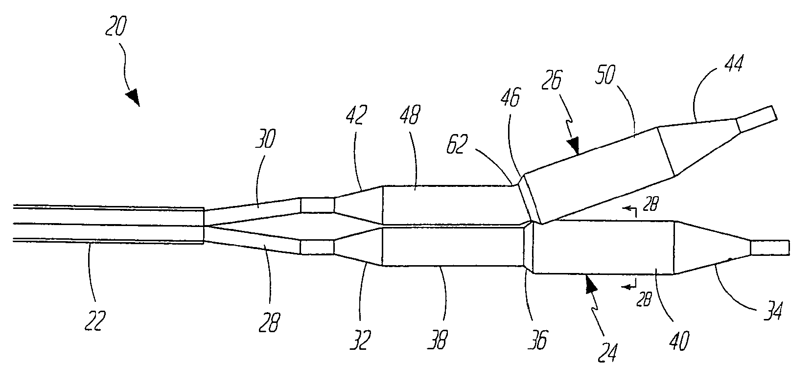
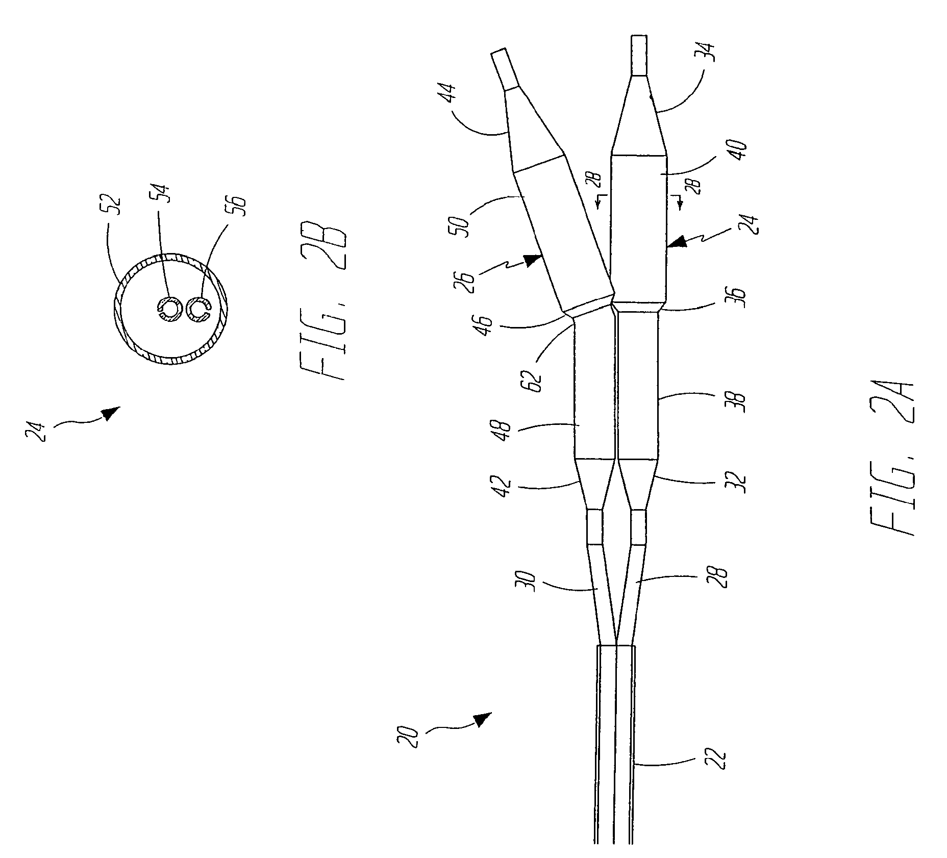
[0027]FIGS. 2A and 2B illustrate a dilatation and stent deployment device 20 in accordance with one aspect of the present invention. Device 20 includes a first sheath 22, and a pair of dilatation balloons 24 and 26. Each dilatation balloon 24 and 26 is coupled to a balloon catheter 28 and 30, respectively, both of which fit within sheath 22. It should also be noted that sheath 22 can be a separate member preferably fixedly disposed about balloon catheters 28 and 30 or can be a dual lumen extrusion which forms part of catheters 28 and 30. In a preferred embodiment, balloons 24 and 26 are similar in construction. Balloon 24 preferably inc...


PUM


Abstract

The present invention provides a dilatation and stent delivery device which tracks over two guidewires. One guidewire is disposed in each branch vessel of a bifurcation. The present invention provides a dilatation and stent delivery device which enables efficient and accurate stent deployment and dilatation of bifurcation lesions.

Description

CROSS-REFERENCE TO RELATED APPLICATIONS[0001]This application is a Continuation application claiming priority from U.S. patent application Ser. No. 10 / 768,561, filed Jan. 30, 2004, which is a Continuation application claiming priority from U.S. patent application Ser. No. 09 / 590,885, filed Jun. 9, 2000 and now abandoned, which is a Continuation application claiming priority from U.S. patent application Ser. No. 09 / 035,642, filed Mar. 5, 1998 and now U.S. Pat. No. 6,099,497, the entire contents of each being expressly incorporated herein by reference.BACKGROUND OF THE INVENTION[0002]The present invention relates to a system for treating vascular disease. More specifically, the present invention relates to a system for treating a lesion at a bifurcation in the vasculature.[0003]Vascular disease currently represents a prevalent medical condition. Typical vascular disease involves the development of a stenosis in the vasculature. The particular vessel containing the stenosis can be comp...

Claims


Application Information

Patent Timeline
Patent Type & Authority Applications(United States)
IPC IPC(8): A61F2/06A61F2/07A61F2/856A61F2/90A61F2/954A61F2/958
CPCA61F2/07A61F2/856A61F2/90A61M2025/1045A61F2/958A61F2002/065A61M2025/1056A61F2/954
Inventor ADAMS, DANIEL O.BLAESER, DAVID J.MATTISON, RICHARD C.
Owner BOSTON SCI SCIMED INC
Learn More