

Valve timing control apparatus
- Summary
- Abstract
- Description
- Claims
- Application Information
AI Technical Summary
Benefits of technology
Problems solved by technology
Method used
Image

Examples
Embodiment Construction
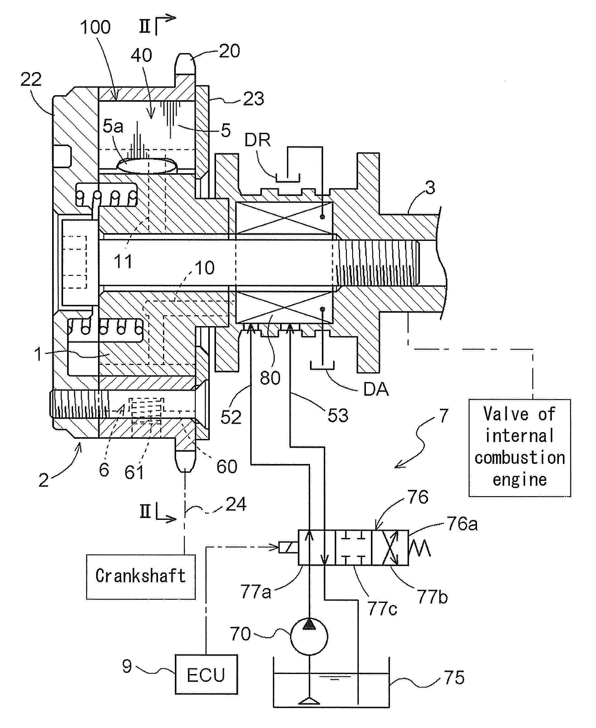
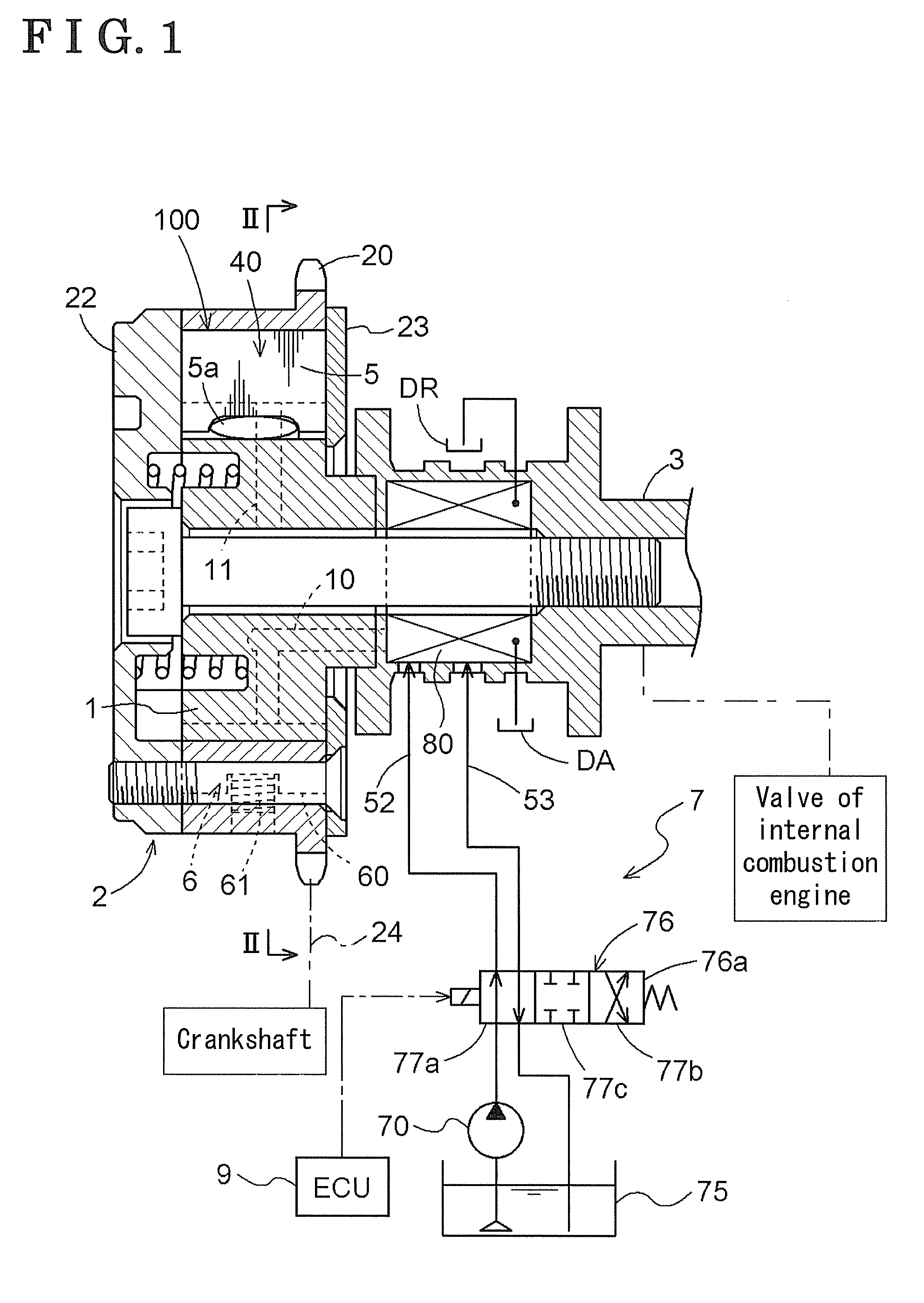
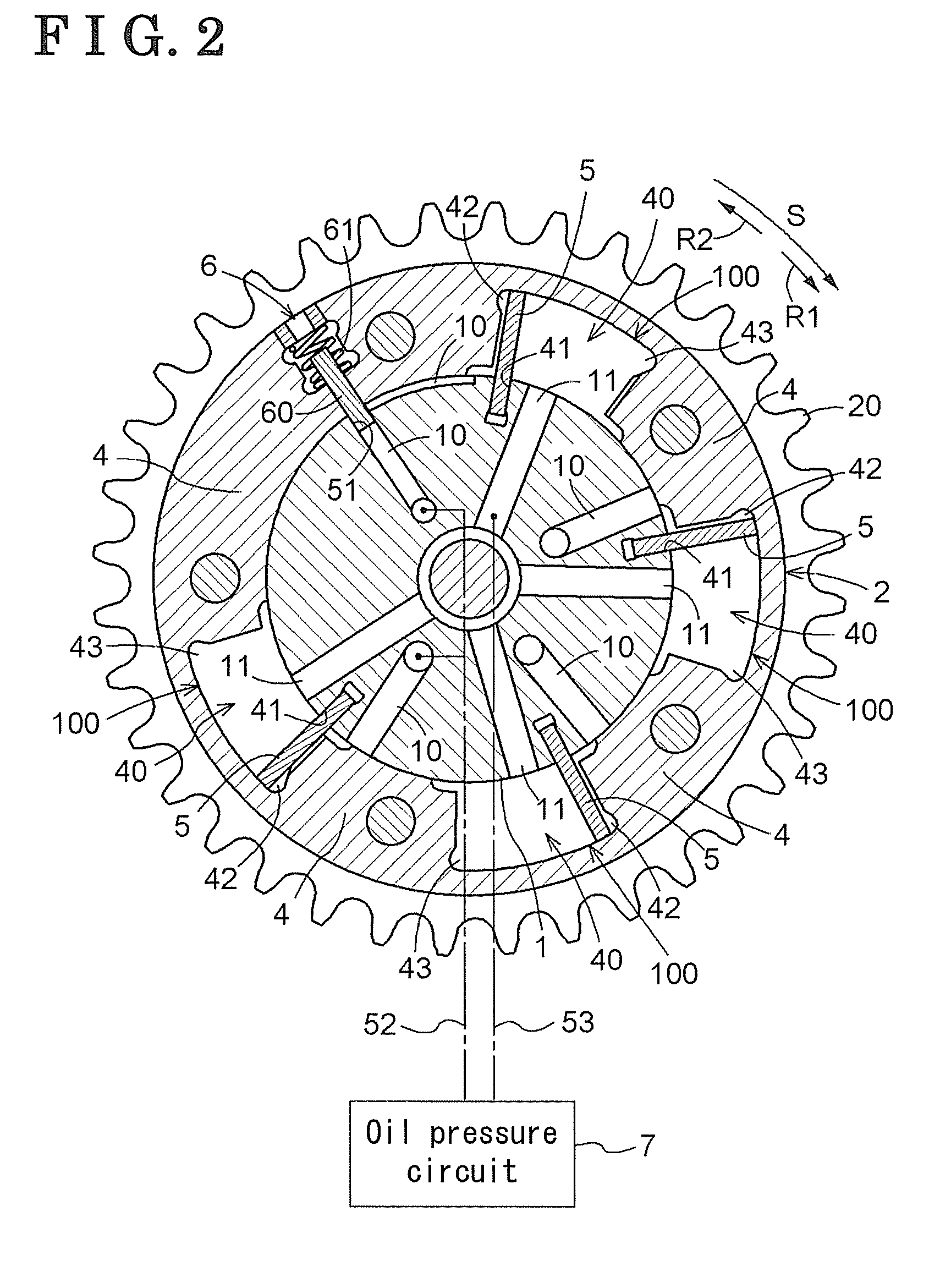
[0016]As shown in FIG. 1, a valve timing control apparatus according to a first embodiment of the invention includes an actuator 100 which is constructed by an external rotor 2 serving as a driving rotation member and an internal rotor 1 serving as a driven rotation member. The external rotor 2 synchronously rotates with a crankshaft of a vehicle engine, and the internal rotor 1 is coaxially arranged with the external rotor 2 and integrally rotates with a camshaft 3. The relative rotation phase between the external rotor 2 and the internal rotor 1 is variably controlled. FIG. 2 is a sectional view taken along a line II-II of FIG. 1.
[0017]The internal rotor 1 is integrally assembled to a distal end of the camshaft 3 which is supported so as to integrally rotate with a cylinder head of the engine. The external rotor 2 sheathes the internal rotor 1 so as to relatively rotate with the internal rotor 1 in a predetermined relative rotation phase range. The external rotor 2 includes a fron...
PUM
 Abstract
Description
Claims
Application Information