
Valve timing control apparatus

a timing control and valve technology, applied in the direction of valve details, valve arrangements, valve drives, etc., can solve the problems of difficult relative rotation phase and insufficient enhancement of the responsiveness of the valve timing control apparatus

Inactive Publication Date: 2011-09-27
AISIN SEIKI KK
View PDF11 Cites 0 Cited by
  • Summary
  • Abstract
  • Description
  • Claims
  • Application Information

AI Technical Summary

Benefits of technology

The present invention relates to a valve timing control apparatus for an internal combustion engine. The apparatus includes a driving rotation member and a driven rotation member that synchronously rotate with the crankshaft and camshaft, respectively, to open and close valves of the engine. An advance angle chamber and a retard angle chamber are defined by the driving rotation member and driven rotation member to control the timing of the valves. The apparatus also includes an oil pump, a passage switching valve, and a drain mechanism to control the supply and discharge of hydraulic fluid to and from the chambers. The technical effect of the invention is to provide precise control over the timing of the valves in an internal combustion engine, leading to improved performance and efficiency.

Problems solved by technology

Accordingly, the rapid displacement of the relative rotation phase becomes difficult, and therefore responsiveness of the valve timing control apparatus is not sufficiently enhanced.

Method used


Image

  • Valve timing control apparatus
  • Valve timing control apparatus
  • Valve timing control apparatus

Examples


Embodiment Construction

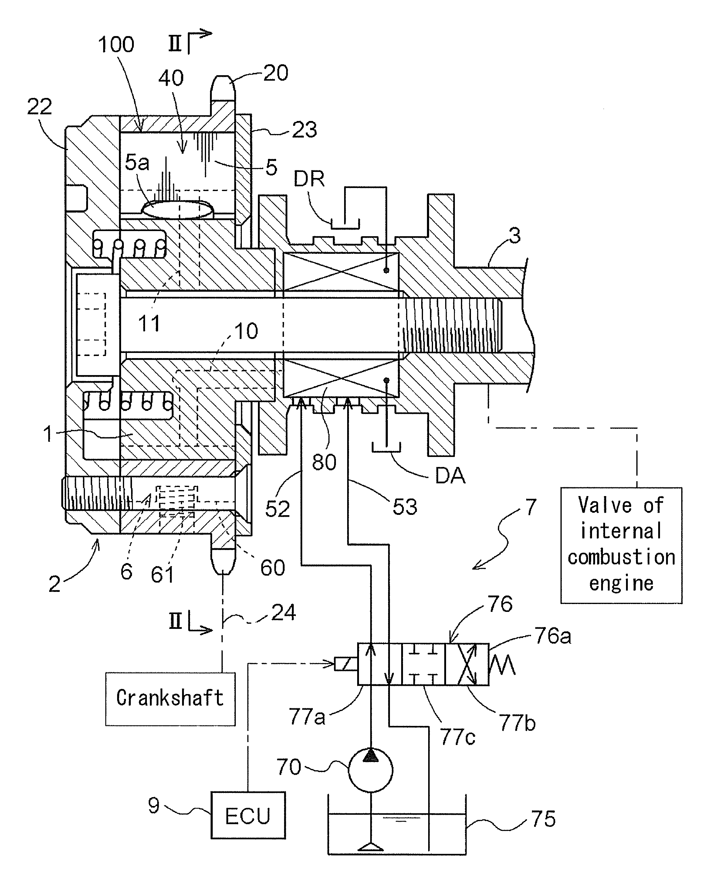
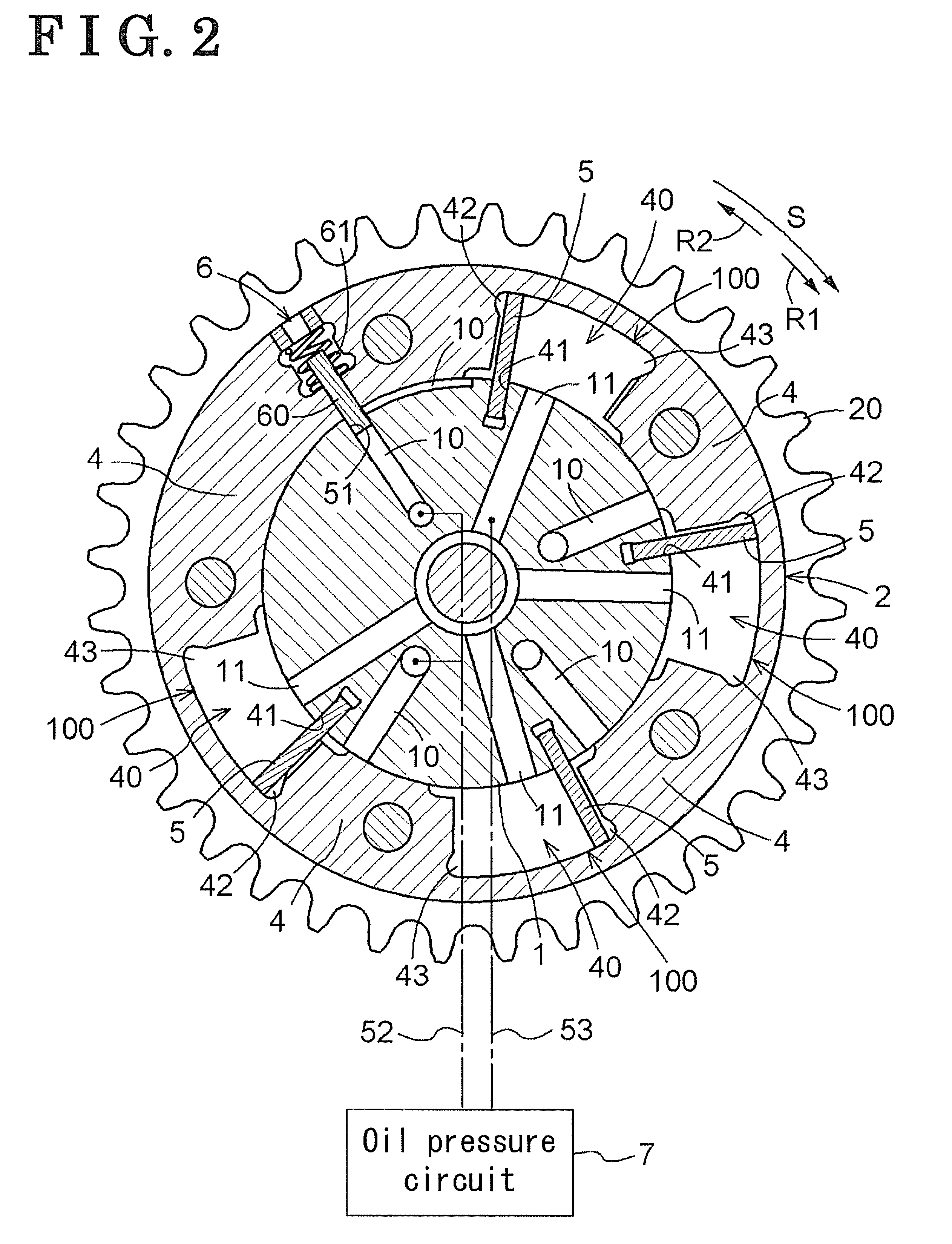
[0016]As shown in FIG. 1, a valve timing control apparatus according to a first embodiment of the invention includes an actuator 100 which is constructed by an external rotor 2 serving as a driving rotation member and an internal rotor 1 serving as a driven rotation member. The external rotor 2 synchronously rotates with a crankshaft of a vehicle engine, and the internal rotor 1 is coaxially arranged with the external rotor 2 and integrally rotates with a camshaft 3. The relative rotation phase between the external rotor 2 and the internal rotor 1 is variably controlled. FIG. 2 is a sectional view taken along a line II-II of FIG. 1.

[0017]The internal rotor 1 is integrally assembled to a distal end of the camshaft 3 which is supported so as to integrally rotate with a cylinder head of the engine. The external rotor 2 sheathes the internal rotor 1 so as to relatively rotate with the internal rotor 1 in a predetermined relative rotation phase range. The external rotor 2 includes a fron...


PUM


Abstract

A valve timing control apparatus includes a driving rotation member, a driven rotation member, an advance angle chamber displacing a rotation phase of the driven rotation member relative to the driving rotation member in an advance angle direction, a retard angle chamber displacing the relative rotation phase in a retard angle direction, an advance angle oil passage, a retard angle oil passage, an oil pump, a passage switching valve switching a position between first and second positions, and a drain mechanism provided between the passage switching valve and at least one of the advance angle chamber and the retard angle chamber to accelerate discharge of the hydraulic fluid from one of the advance angle chamber and the retard angle chamber when the hydraulic fluid is supplied to the other of the advance angle chamber and the retard angle chamber.

Description

CROSS REFERENCE TO RELATED APPLICATIONS[0001]This application is based on and claims priority under 35 U.S.C §119 with respect to Japanese Patent Application 2007-317086, filed on Dec. 7, 2007, the entire content of which is incorporated herein by reference.FIELD OF THE INVENTION[0002]This invention relates to a valve timing control apparatus.BACKGROUND[0003]A valve timing control apparatus is disclosed in JP H10-280919A. In the valve timing control apparatus disclosed in Paragraph 0029 and FIG. 1 of JP H10-280919A, for example, when a hydraulic fluid is supplied from an advance angle oil passage to an advance angle chamber for displacing the relative rotation phase in an advance angle direction, the hydraulic fluid in a retarded angle chamber is discharged from a retard angle oil passage to an oil pan through a one way drain control passage and a fourth port of a passage switching valve. Then, a pressure of the retard angle chamber becomes low and the relative rotation phase is dis...

Claims


Application Information

Patent Timeline
Patent Type & Authority Patents(United States)
IPC IPC(8): F01L1/34
CPCF01L1/3442F01L2001/0476F01L2001/34426F01L2001/34483
Inventor NOGUCHI, YUJI
Owner AISIN SEIKI KK
Features
  • Generate Ideas
  • Intellectual Property
  • Life Sciences
  • Materials
  • Tech Scout
  • Unparalleled Data Quality
  • Higher Quality Content
  • 60% Fewer Hallucinations
Learn More