Faucet generator
- Summary
- Abstract
- Description
- Claims
- Application Information
AI Technical Summary
Benefits of technology
Problems solved by technology
Method used
Image

Examples
first embodiment
[0050]Hereinafter, the invention will be described with reference to FIGS. 1 to 24. In the figures, identical components are denoted by the same reference numerals.
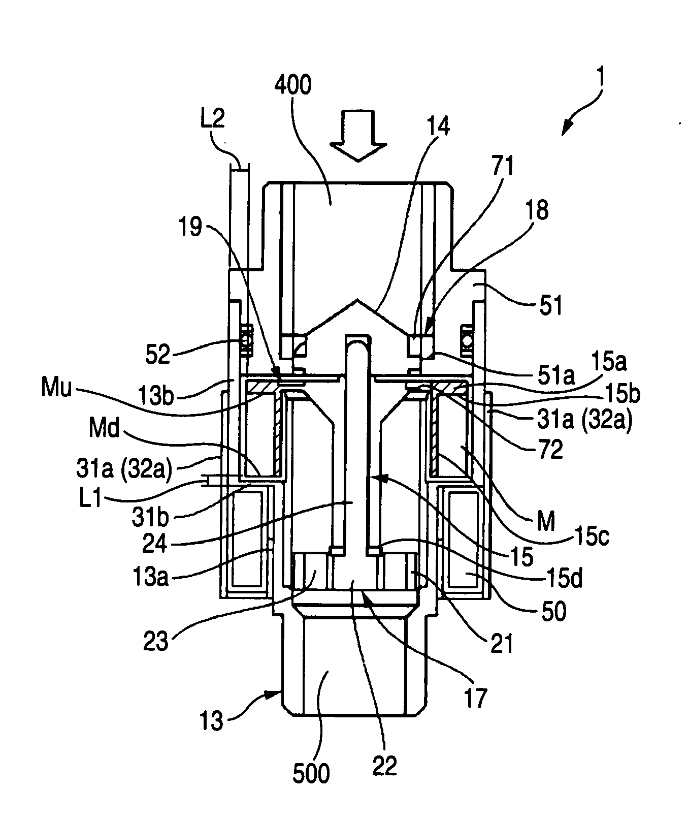
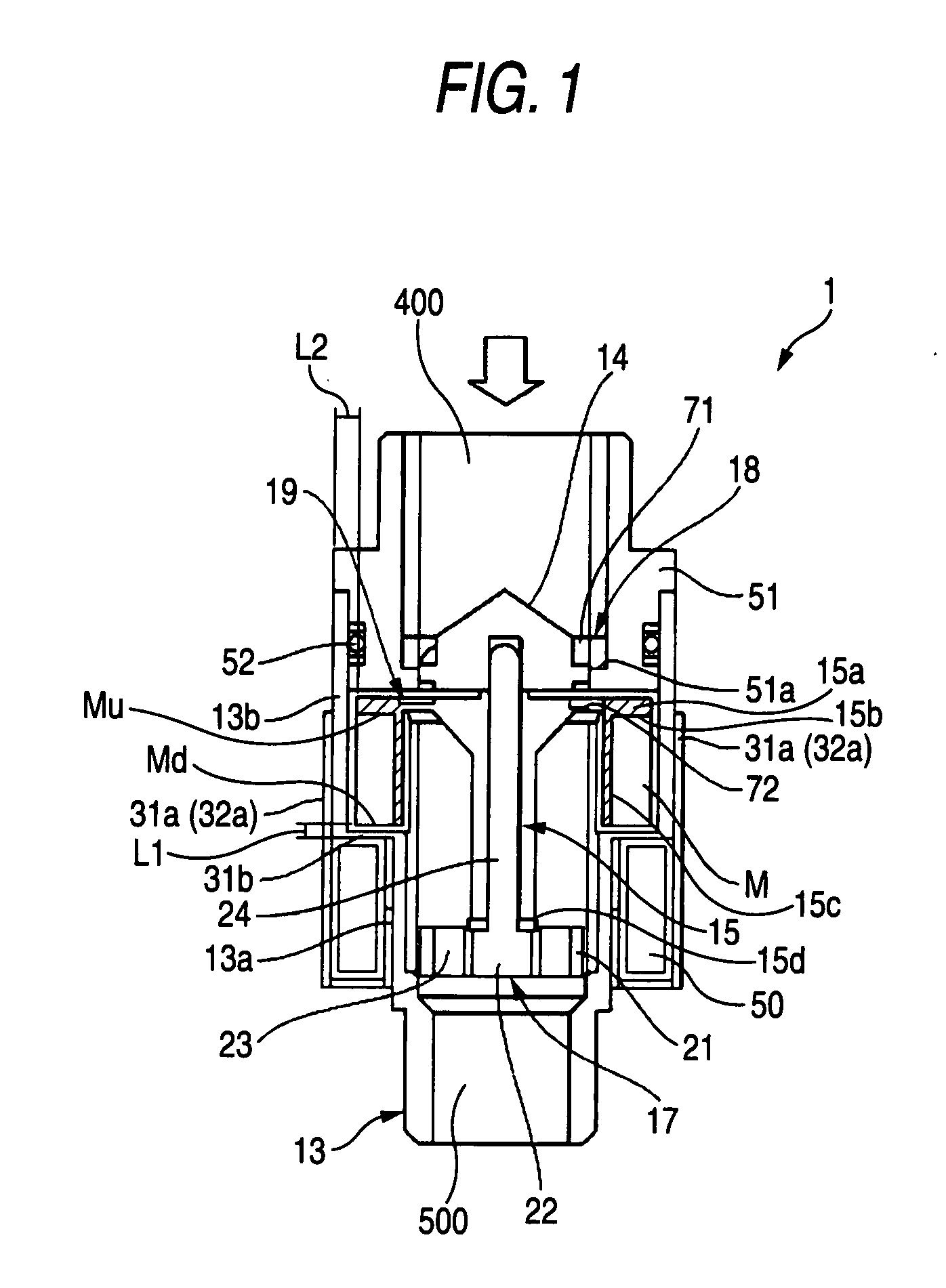
[0051]FIG. 1 is a schematic sectional view of a generator 1 of the first embodiment of the invention.
[0052]The generator 1 includes a water inflow port 400, a water outflow port 500, a cylindrical body 13, a pre-rotation stator vane 14, a rotor vane 15, a magnet M, a coil 50, and a sealing member 51. These components are housed in a case 12 (see FIG. 3). The arrow which is drawn above the pre-rotation stator vane 14 indicates the direction of the water flow.
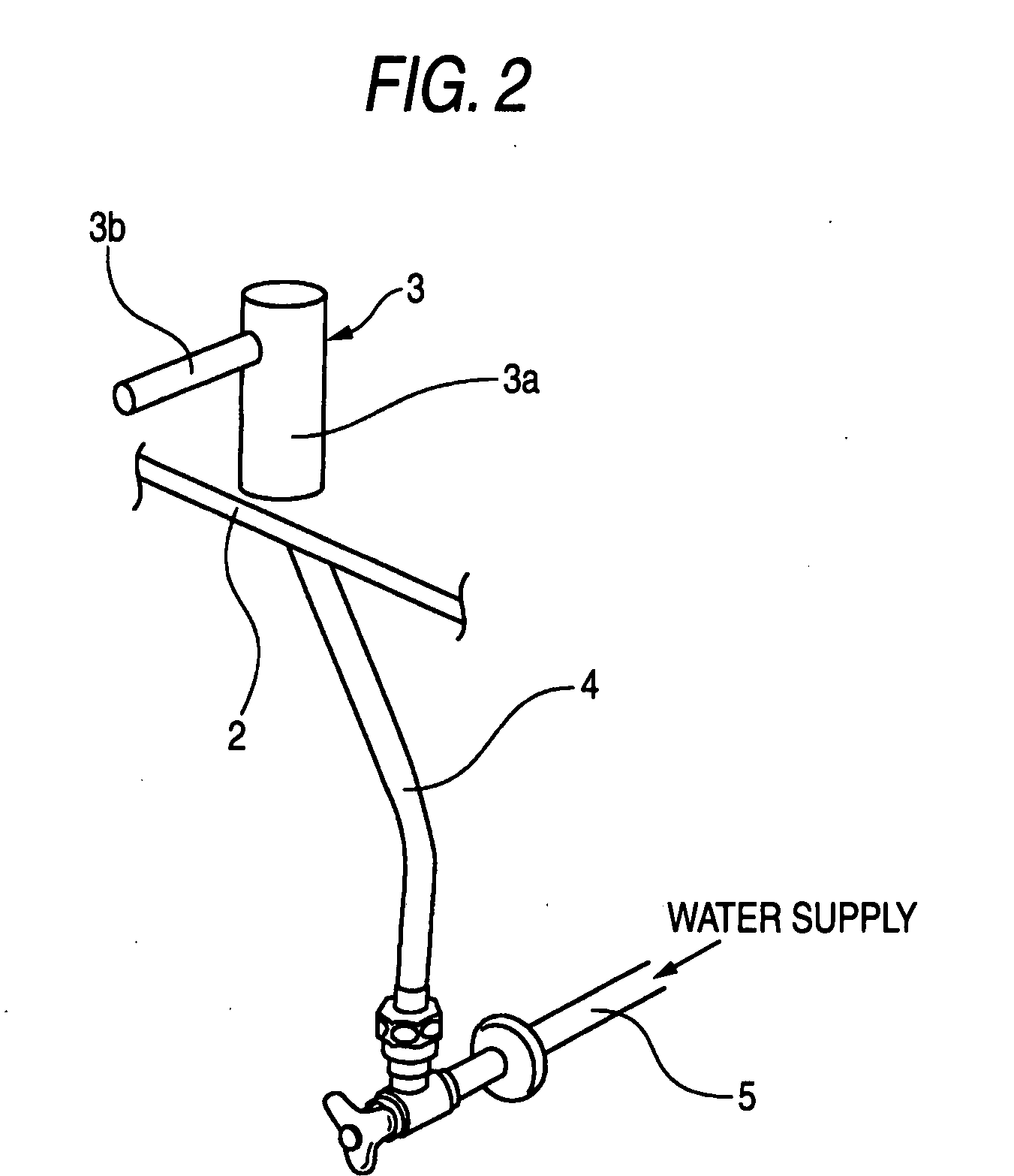
[0053]Prior to description of the generator 1, an automatic faucet apparatus 3 including the generator 1 will be described.
[0054]FIG. 2 is a schematic view illustrating an example of mounting of the automatic faucet apparatus 3, and FIG. 3 is a schematic sectional view of the automatic faucet apparatus 3. In the figures, the arrows indicate the direction of the water f...
second embodiment
[0141]Hereinafter, the invention will be described with reference to FIGS. 25 to 31. In the drawings, identical components are denoted by the same reference numerals.
[0142]The second embodiment of the invention provides a faucet generator wherein the generator includes: a rotor vane which has a rotation center that is substantially parallel to a water supply channel, and which is disposed in the water supply channel to be rotatable about the rotation center; a magnet which is disposed to surround the rotor vane, and which is rotatable integrally with the rotor vane; a stator which is disposed to be opposed to an axial end face of the magnet, and which has a yoke and an inductor; a coil which is disposed in the stator, and in which an electromotive force is produced by rotation of the magnet; and a shaft supporting portion which supports, in an axial direction, a center shaft that is substantially parallel to the water supply channel, an outer circumferential face of the magnet is ma...
third embodiment
[0199]Hereinafter, the invention will be described with reference to FIGS. 32 to 39. In the drawings, identical components are denoted by the same reference numerals.
[0200]The third embodiment of the invention provides a faucet generator wherein the generator includes: a rotor vane which has a rotation center that is substantially parallel to a water supply channel, and rotor vane blades that are disposed in the water supply channel to be rotatable about the rotation center; a magnet which is disposed in a radially outward direction of the rotor vane blades, and which is rotatable integrally with the rotor vane; a coil in which an electromotive force is produced by rotation of the magnet; and a stator having: a yoke which is disposed to surround the coil; and a plurality of inductors which extend from the yoke, and which are disposed to be separated from one another, and downstream end faces of the rotor vane blades are separately disposed to be positioned on the upstream side of th...
PUM
 Abstract
Description
Claims
Application Information
 - R&D Engineer
- R&D Manager
- IP Professional
- Industry Leading Data Capabilities
- Powerful AI technology
- Patent DNA Extraction
Browse by: Latest US Patents, China's latest patents, Technical Efficacy Thesaurus, Application Domain, Technology Topic.
© 2024 PatSnap. All rights reserved.Legal|Privacy policy|Modern Slavery Act Transparency Statement|Sitemap