
Controlling congestion in a packet switched data network

a packet switched data network and congestion control technology, applied in data switching networks, frequency-division multiplexes, instruments, etc., can solve the problems of high latency, difficult to achieve the optimization of buffer sizes in routers, switches or bridges, and higher costs for those network elements that include, so as to reduce congestion, reduce congestion, and reduce likelihood

Active Publication Date: 2009-06-11
RPX CORP
View PDF6 Cites 38 Cited by
  • Summary
  • Abstract
  • Description
  • Claims
  • Application Information

AI Technical Summary

Benefits of technology

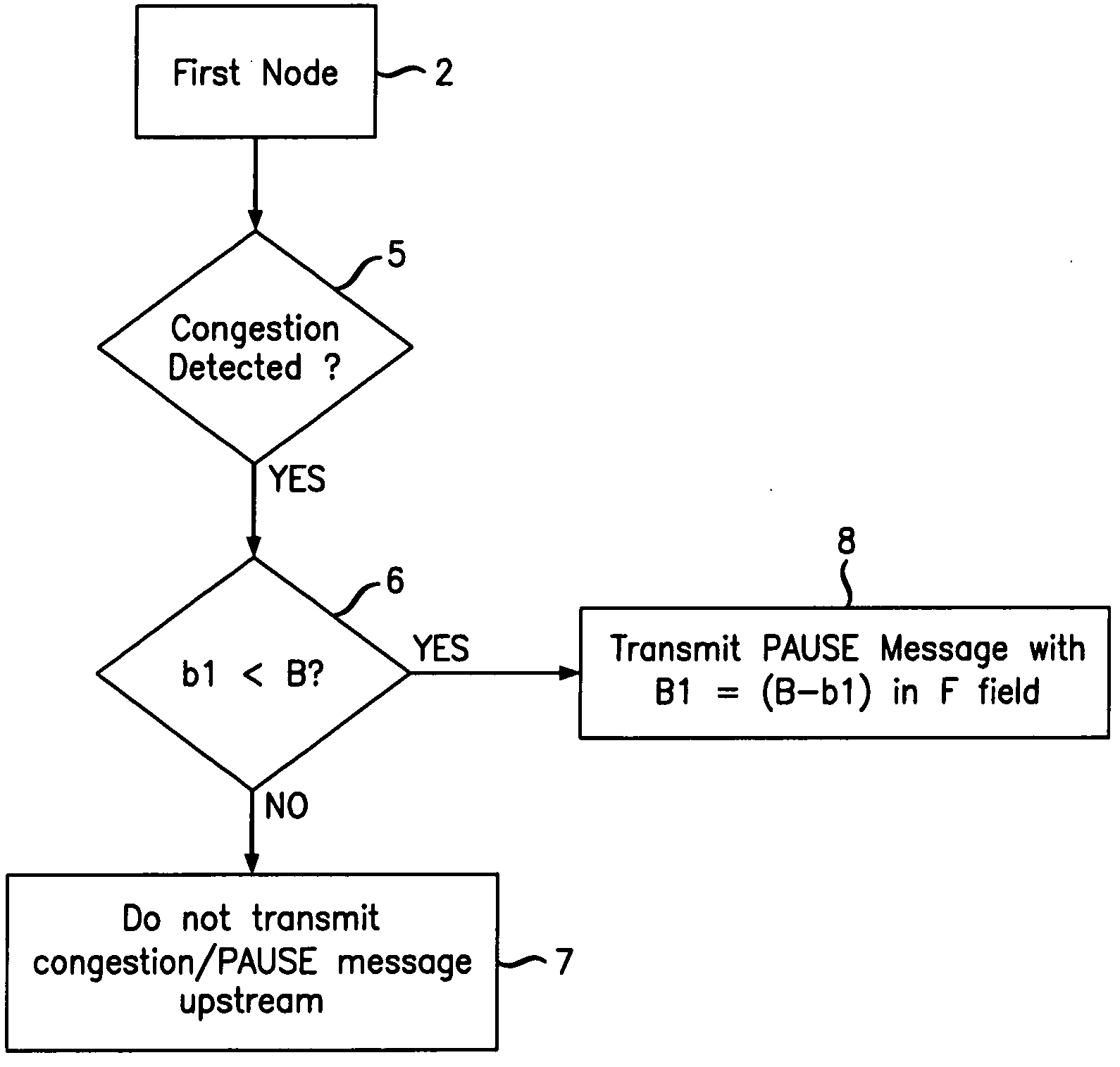
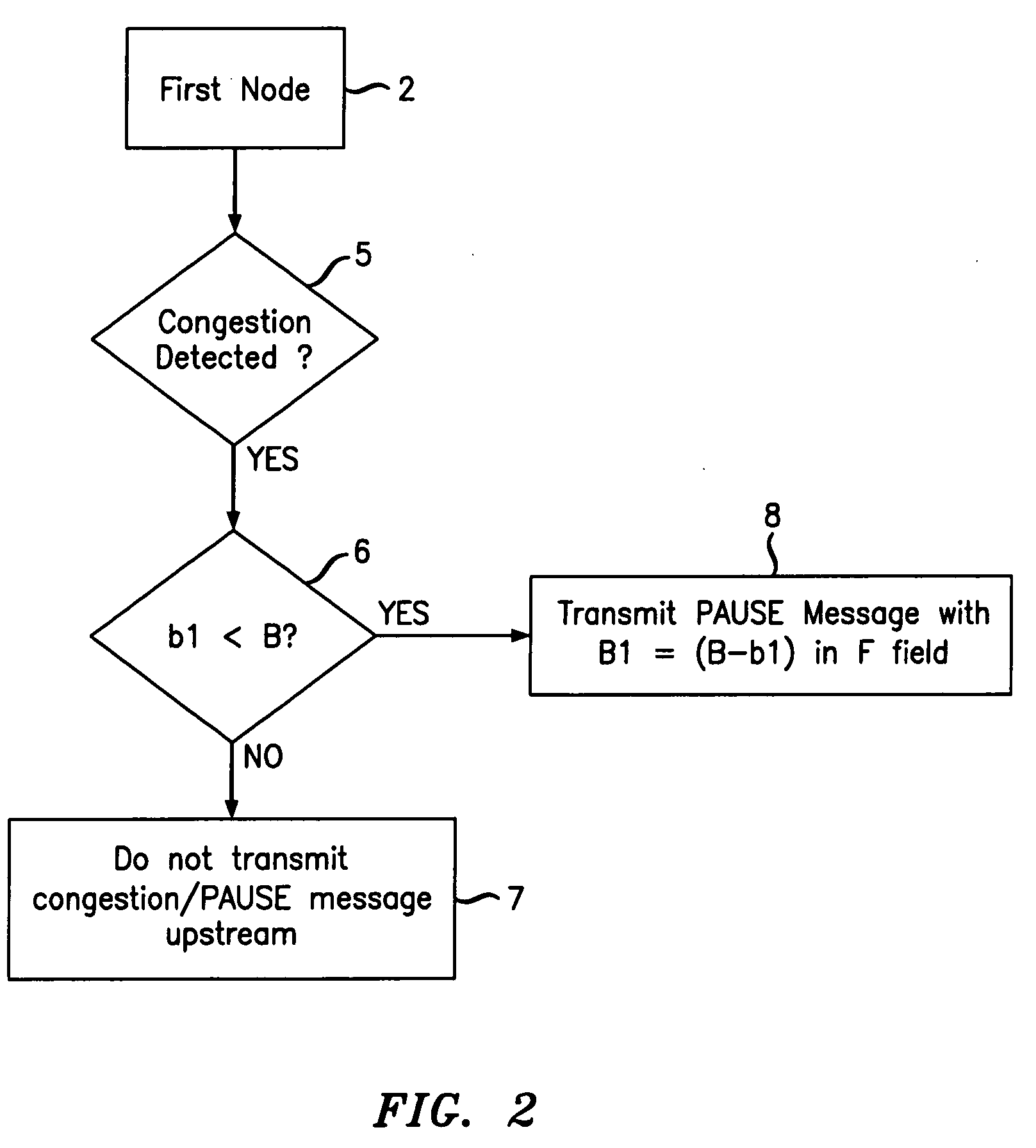
[0005]The second node may drop packets to reduce congestion. In another variant in accordance with the invention, where the buffer capacity of the second node is less than that required, a pause message is sent to a third node, upstream from the second node, thus acting to reduce the congestion. Where the buffer capacity of the second node is also less than that required, information may be sent to the third node indicating the amount of buffer space required taking into account the buffer capacity of the second node. As the required buffer size is modified depending on the capacity of a number of nodes involved, and a pause message is transmitted upstream only when a particular node in a chain is unable to meet that required capacity, the pause message is less likely to spread in an uncontrolled manner. Thus, by using the invention, there is a reduced likelihood that the entire network will become jammed.

Problems solved by technology

Optimization of buffer sizes in routers, switches or bridges is difficult to achieve.
Excessively large buffers lead to higher costs for those network elements that include them and also to performance issues such as high latency.
In contrast, small buffers are cheaper but also increase packet loss for unpredictable bursty traffic.
Thus, when there is congestion, it may lead to utilizing buffers at multiple nodes to hold packets.
There is a risk that, under some conditions, utilizing the PAUSE mechanism may jam an entire network as the PAUSE instruction propagates upstream over multiple nodes.

Method used


Image

  • Controlling congestion in a packet switched data network
  • Controlling congestion in a packet switched data network
  • Controlling congestion in a packet switched data network

Examples


Embodiment Construction

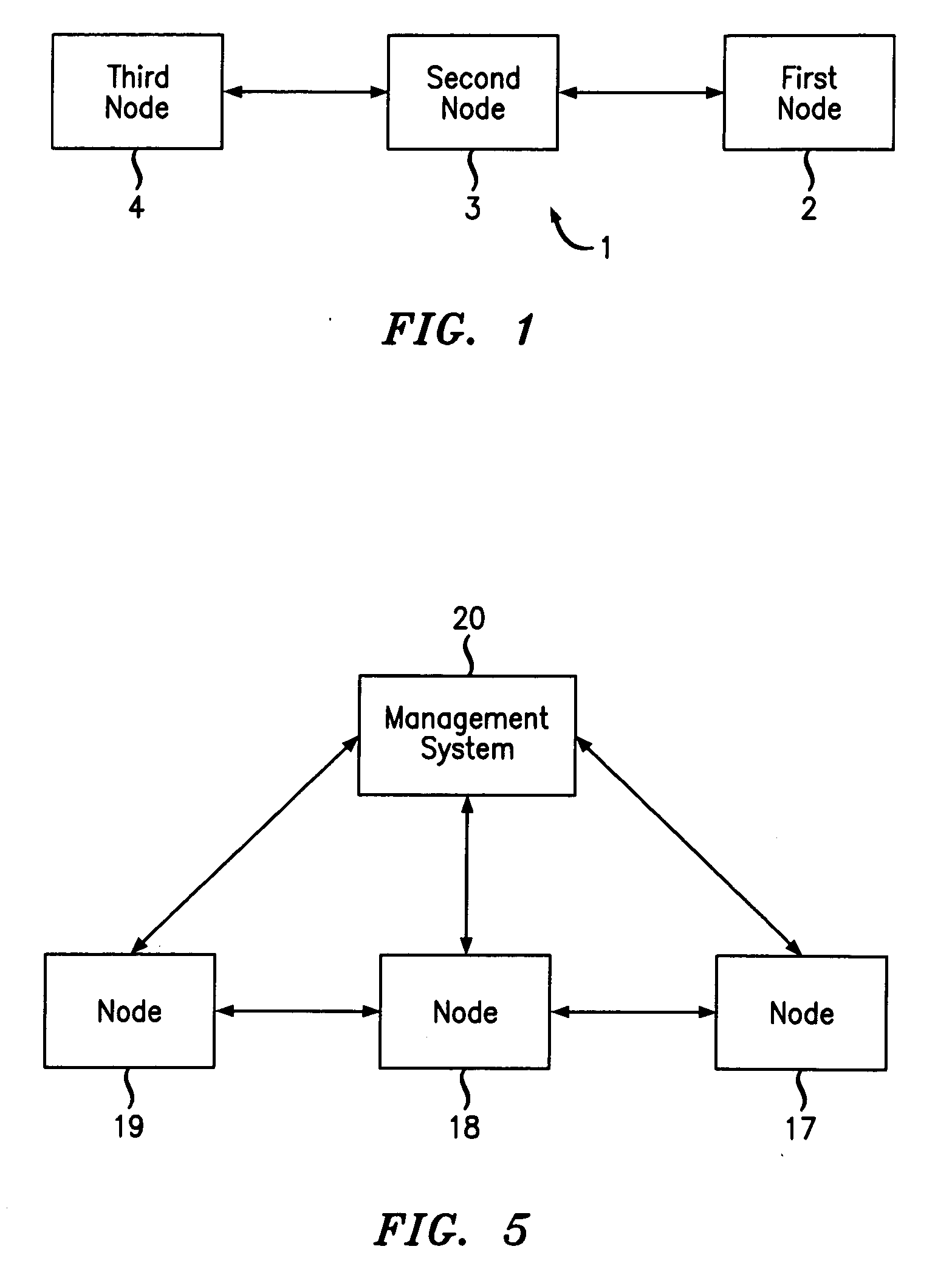
[0017]With reference to FIG. 1, a data network 1 operating in accordance with the Ethernet protocol includes a plurality of nodes 2, 3 and 4, each of which includes a buffer at which frames are temporarily stored. Each node has an indicator for detecting the amount of the buffer capacity that is occupied and the amount which is free and available to be used to hold incoming data packets. The nodes may be routers, switches, bridges, or other network elements where data packets are required to be held. The first node 2 is downstream of the second node 3, receiving data packets therefrom. Similarly, the second node 3 is downstream of a third node 4. In practice, a node may connect to more than one other node in an upstream or downstream direction.

[0018]The first node 2 receives frames, or data packets, from the second node 3. If these are transmitted at too great a rate, the first node 2 becomes congested because there is insufficient buffer space remaining at the first node 2. The exi...


PUM


Abstract

A method of controlling congestion in a packet switched network includes transmitting a pause message to a node upstream of a congested node to instruct it to cease sending for a period of time. The congested node also sends information to the upstream node informing it of the buffer size required to relieve congestion. If the buffer capacity of the upstream node is greater than or equal to the signalled amount required, no further action is taken. If the buffer capacity of the upstream node is less that the required amount, it in turn sends a pause message to a node upstream of it, together with an indication of the required buffer size to reduce congestion, taking into account the amount available from the sending nodes.

Description

FIELD OF THE INVENTION[0001]The present invention relates to a method of controlling congestion in a packet switched data network and to a network using such a method.BACKGROUND OF THE INVENTION[0002]Optimization of buffer sizes in routers, switches or bridges is difficult to achieve. Excessively large buffers lead to higher costs for those network elements that include them and also to performance issues such as high latency. In contrast, small buffers are cheaper but also increase packet loss for unpredictable bursty traffic. For higher layer applications like Transmission Control Protocol (“TCP”), used, for example, for file transfers and web-browsing, packet loss triggers a reduction in traffic sending rate. This in turn causes lower throughput and greater file download and response times. The effect of buffer size on TCP performance is dependent on a number of parameters and on the specific circumstances, taking into account traffic and network configuration. A paper by D. Wisc...

Claims


Application Information

Patent Timeline
IPC IPC(8): H04L12/56H04L47/30
CPCH04L47/10H04L47/17H04L47/35H04L47/30H04L47/26
Inventor MALHOTRA, RICHA
Owner RPX CORP
Learn More