Spinal implants and methods

a technology for intervertebral discs and implants, applied in the field of spinal implants, can solve the problems of loss of disc space, more problematic annulus defects, and source of continued or new lumbar spine generated pain

Inactive Publication Date: 2009-06-11
MAGELLAN SPINE TECH
View PDF99 Cites 220 Cited by
  • Summary
  • Abstract
  • Description
  • Claims
  • Application Information

AI Technical Summary

Benefits of technology

[0015]A more desirable solution entails replacing, in part or as a whole, the damaged nucleus with a suitable prosthesis having the ability to complement the normal height and motion of the disc while stimulating, at least in part, natural disc physiology. Disclosed embodiments of the present spinal implants and methods of providing dynamic stability to the spine have several features, no single one of which is solely responsible for their desirable attributes. Without limiting the scope of these spinal implants and methods as expressed by the claims that follow, their more prominent features will now be discussed briefly. After considering this discussion, and particularly after reading the section entitled “Detailed Description,” one will understand how the features of the disclosed embodiments provide advantages, which include, inter alia, the capability to repair annular defects and stabilize adjacent motion segments of the spine without substantially diminishing the range of motion of the spine, simplicity of structure and implantation, and a low likelihood that the implant will migrate from the implantation site.
[0016]The implant can be fabricated from materials such as biocompatible metals such as titanium, stainless steel, or cobalt nickel alloys, or it can comprise biocompatible polymers such as polyetheretherketone, polyester, and polysulfone. The implant can further comprise biodegradable / erodable materials such as polylactic acid, polyglycolic acid, sugars, collagen, and the like. The axially elongate structure can comprise rigid materials or it can be compressible to assist with the maintenance of spine mobility.
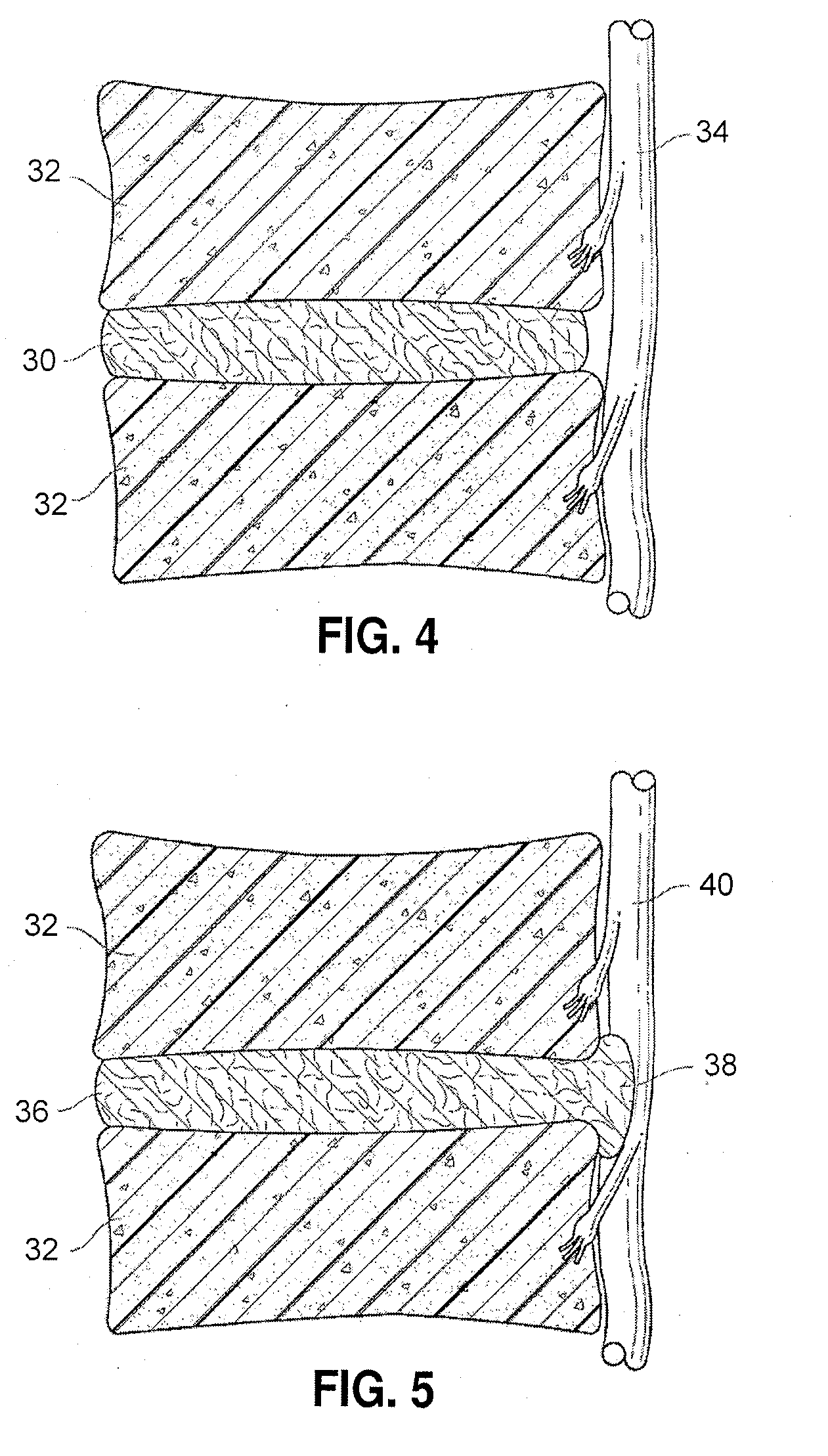
[0017]In some embodiments, the implant can be suited for a population of patients who have pain from an unruptured hernia (bulge) that can be decompressed by implanting a distraction device separating the vertebrae enough to pull the bulge in and relieving the disc of axial compression, and perhaps allowing the disc to re-hydrate. The decompression feature of the device can assist in preventing future herniation. In some embodiments, the implant can further serve as a stabilizer for the spine since it can be configured to apply support uniformly from left to right. Further, the implant can preserve some motion in the spine since the spine can still hinge forward or backward about the device to at least some extent. The axially elongate implant can serve as this distraction device. The location of the implant can be at the center of flexion-extension and the implant can serve as a barrier against re-herniation along the entire length of the internal posterior wall of the annulus. In some embodiments, a single implant can be placed to separate, or distract, the vertebrae. In some embodiments, a plurality of implants can be placed to separate the vertebrae. In certain embodiments, two implants can be placed, one on each side of the posterior portion of the spine, to stabilize the spine laterally and to provide one or more of the functions of decompression, vertebral distraction, facet unloading, nerve decompression, and disc height preservation or restoration. In some embodiments, the implants can have their longitudinal axes oriented generally laterally with regard to the anatomic axis of the spine. In some embodiments, the implants can have their longitudinal axes oriented generally in the approximate anterior or posterior direction. In certain embodiments, the implants can have their longitudinal axes oriented radially with respect to the geometric center of the intervertebral disc. In some embodiments, these devices can provide for motion preservation of the spine segment within which the devices are implanted. In certain embodiments, the implants can partially or totally restrict motion within that segment. In some embodiments, the implants can be used in conjunction with spinal fusion procedures to maintain early postoperative stability of spinal support. In certain embodiments, the implant can reside totally within the outer boundary of the annulus of the intervertebral disc. In some embodiments, the implant can reside with a portion of its structure external to the outer boundary of the intervertebral disc annulus. In some embodiments, the decompression devices are placed using a posterior access. In some embodiments, the decompression devices are placed using posteriolateral access. In some embodiments, the decompression devices are placed using anterior or anteriolateral access.

Problems solved by technology

Loss of disc space height can also be a source of continued or new lumbar spine generated pain.
Further, a more problematic annulus defect concern arises in the realm of annulotomies encountered as part of a surgical procedure performed on the disc space.
As these overlapping laminated plies of the annulus begin to buckle and separate, either circumferential or radial annular tears can occur, which may contribute to persistent and disabling back pain.
Adjacent, ancillary spinal facet joints can also be forced into an overriding position, which can create additional back pain.
While this treatment can alleviate the pain, all discal motion is lost in the fused segment.
Ultimately, this procedure places greater stress on the discs adjacent the fused segment as they compensate for the lack of motion, perhaps leading to premature degeneration of those adjacent discs.

Method used


Image

  • Spinal implants and methods
  • Spinal implants and methods
  • Spinal implants and methods

Examples


Embodiment Construction

,” one will understand how the features of the disclosed embodiments provide advantages, which include, inter alia, the capability to repair annular defects and stabilize adjacent motion segments of the spine without substantially diminishing the range of motion of the spine, simplicity of structure and implantation, and a low likelihood that the implant will migrate from the implantation site.

[0016]The implant can be fabricated from materials such as biocompatible metals such as titanium, stainless steel, or cobalt nickel alloys, or it can comprise biocompatible polymers such as polyetheretherketone, polyester, and polysulfone. The implant can further comprise biodegradable / erodable materials such as polylactic acid, polyglycolic acid, sugars, collagen, and the like. The axially elongate structure can comprise rigid materials or it can be compressible to assist with the maintenance of spine mobility.

[0017]In some embodiments, the implant can be suited for a population of patients w...


PUM


Abstract

Spinal implants are disclosed that can be used for annular repair, facet unloading, disc height preservation, disc decompression, or for sealing a portal through which an intervertebral implant was placed. In some embodiments, an implant is placed within the intervertebral disc space, primarily within the region of the annulus fibrosus. In some embodiments, the implant is expandable. In some embodiments, the implant has a sealing tail structure comprising a tail flange and a linkage. In some embodiments, the sealing tail structure limits the extrusion or expulsion of disc material, either annulus fibrosus or nucleus, into the posterior region of the spine where it could impinge on nerves. In some embodiments, the tail structure is retained in place within the annulus fibrosus by means of an anchor. In some embodiments, the anchor is constructed from multiple components.

Description

CROSS-REFERENCE TO RELATED APPLICATIONS[0001]This application claims priority to U.S. Provisional Patent App. No. 61 / 032,921, filed on Feb. 29, 2008, which in turn claims priority to U.S. Provisional Patent App. No. 61 / 016,417, filed on Dec. 21, 2007, which in turn claims priority to U.S. Provisional Patent App. No. 60 / 989,100, filed on Nov. 19, 2007, the entire contents of all of these applications are herein incorporated by reference.BACKGROUND[0002]1. Field[0003]The present disclosure relates to devices and methods for treating intervertebral discs using implants.[0004]2. Description of the Related Art[0005]The vertebral spine is the axis of the skeleton upon which all of the body parts “hang,” or are supported. In humans, the normal spine has seven cervical, twelve thoracic, and five lumbar segments. Functionally each segment can be thought of as comprising an intervertebral disc, sandwiched between two vertebral bodies. The lumbar segments sit upon a sacrum, which then attaches...

Claims


Application Information

Patent Timeline
Patent Type & Authority Applications(United States)
IPC IPC(8): A61F2/44
CPCA61B17/1615A61F2310/00011A61B2017/00261A61B2019/461A61B2019/462A61F2/442A61F2/4611A61F2/4684A61F2002/2835A61F2002/30112A61F2002/30113A61F2002/30242A61F2002/30383A61F2002/30405A61F2002/30448A61F2002/30462A61F2002/30481A61F2002/30565A61F2002/30574A61F2002/30576A61F2002/30604A61F2002/30616A61F2002/30787A61F2002/3085A61F2002/30892A61F2002/4435A61F2002/4475A61F2002/4629A61F2002/4677A61F2220/0025A61F2220/005A61F2220/0075A61F2230/0004A61F2230/0006A61F2230/0071A61B17/1671A61F2002/30593A61B2090/061A61B2090/062
Inventor CONNER, E. SCOTTLENKER, JAY A.NGUYEN, KHOIVALKO, JEFFREY J.LAKE, MATTHEW SCOTTDAVIS, PETER GREGORY
Owner MAGELLAN SPINE TECH
Why Eureka
Try Eureka