
Garden tool head with coated leading edge

a technology of leading edge and tool head, applied in the field of garden tool head, can solve problems such as rough appearance and specks, and achieve the effect of enhancing the visual appearance of the coated portion and conserving the hardness enhancing material

Active Publication Date: 2009-06-18
IAMS
View PDF9 Cites 2 Cited by
  • Summary
  • Abstract
  • Description
  • Claims
  • Application Information

AI Technical Summary

Benefits of technology

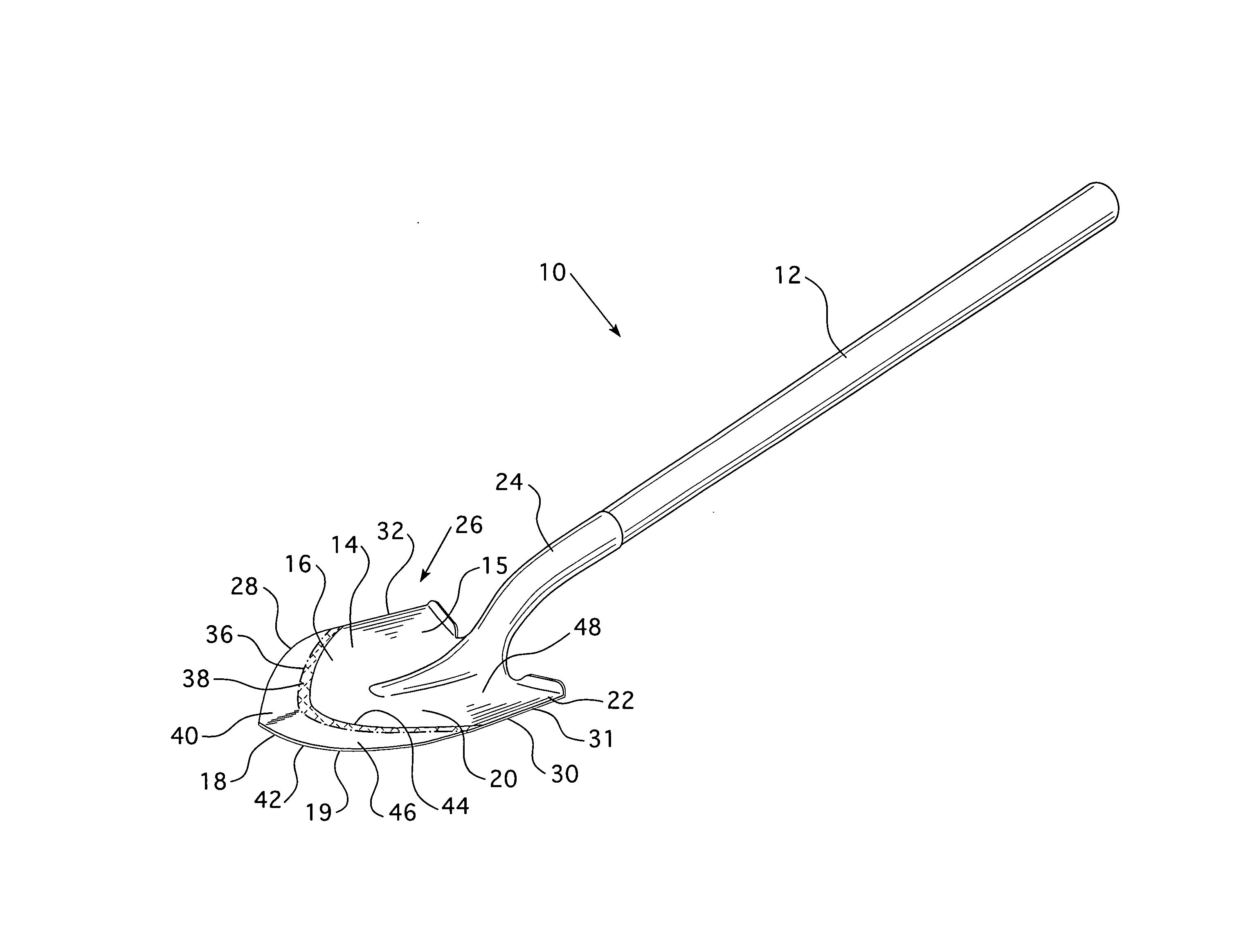
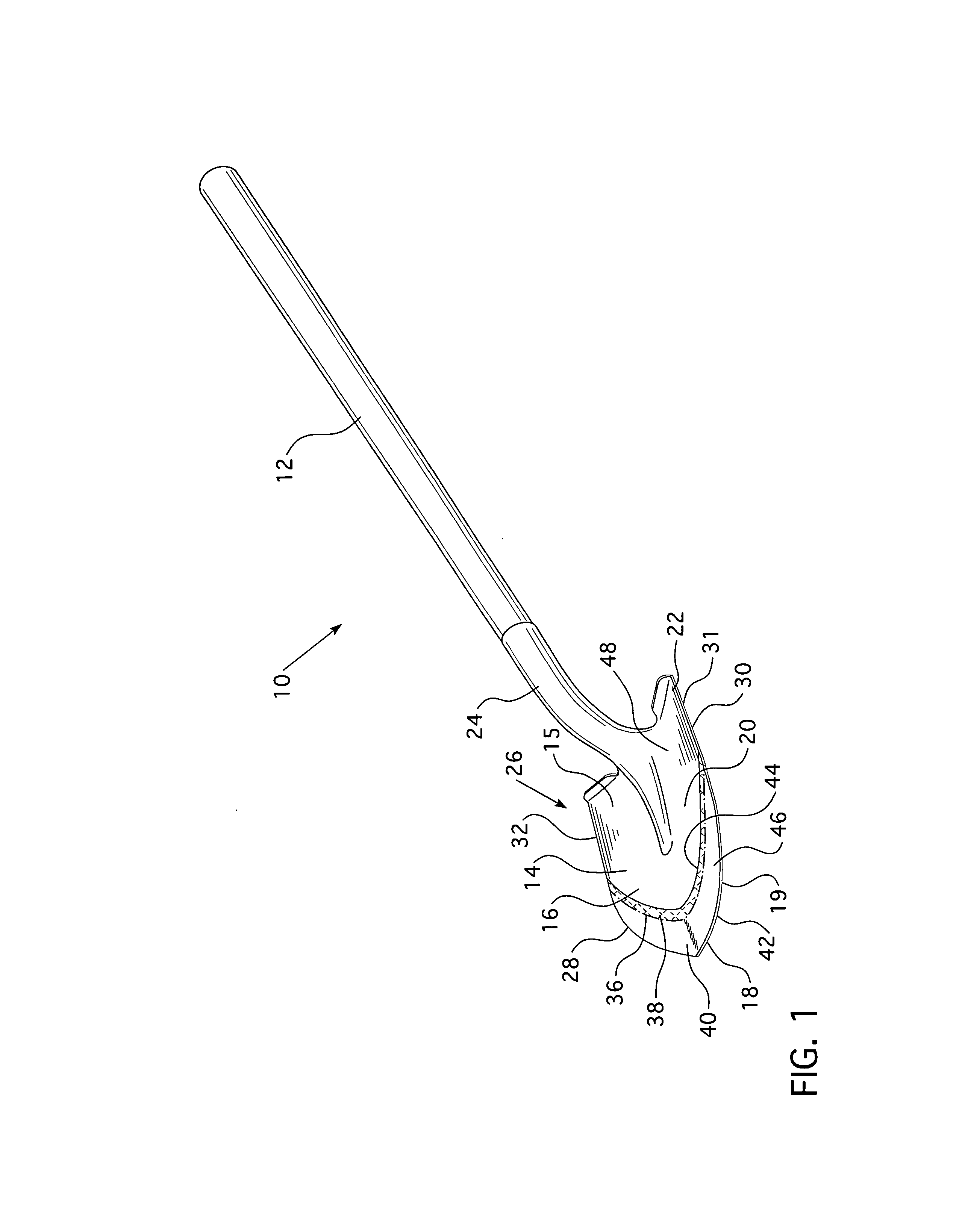
[0005]The concept disclosed herein provides for a garden tool wherein the leading edge of the tool head has a leading edge coated with a hardness enhancing material. Preferably, the coating is selected from the group comprising: all performance or appearance enhancing coatings including but not limited to tungsten alloys, carbide alloys, titanium alloys, chromium alloys, steel alloys including stainless steels, brass alloys, copper alloys, bronze alloys and ceramics. The coating is preferably applied by a high velocity oxy-fuel process or an electric arc spray. Using such application methods the body of the tool head may be masked to provide a clean line of demarcation between the coated portion and the non-coated portion. The coated portion is, typically, a different color than the metal tool head. Further, the coating material may have a dye, or other coloring agent incorporated therein, to enhance the visual appearance of the coated portion. Further, while the coating is, preferably, generally smooth, the coating process and / or material may include particulate matter that results in a gritty or specked appearance.
[0006]The coating may be applied by other means such as, but not limited to, dipping in a reservoir of liquid, plasma spray coating, plasma transferred arc, gas detonation coating, cold gas coating, plating or deposition methods. Such an application method typically results in a generally straight, laterally extending border between the coated portion and non-coated portion of the tool head. However, masking may still be used on the tool head to define the shape of the coated portion. Further, depending upon the nature of the hardness enhancing material, masking may be used to conserve the hardness enhancing material. For example, if the hardness enhancing material is initially in a water based solution, a hydrophobic masking material may be used to repel the hardness enhancing material from the masked material and return the liquid to the reservoir as the tool head is lifted from the reservoir.

Problems solved by technology

Further, while the coating is, preferably, generally smooth, the coating process and / or material may include particulate matter that results in a gritty or specked appearance.

Method used


Image

  • Garden tool head with coated leading edge
  • Garden tool head with coated leading edge
  • Garden tool head with coated leading edge

Examples


Embodiment Construction

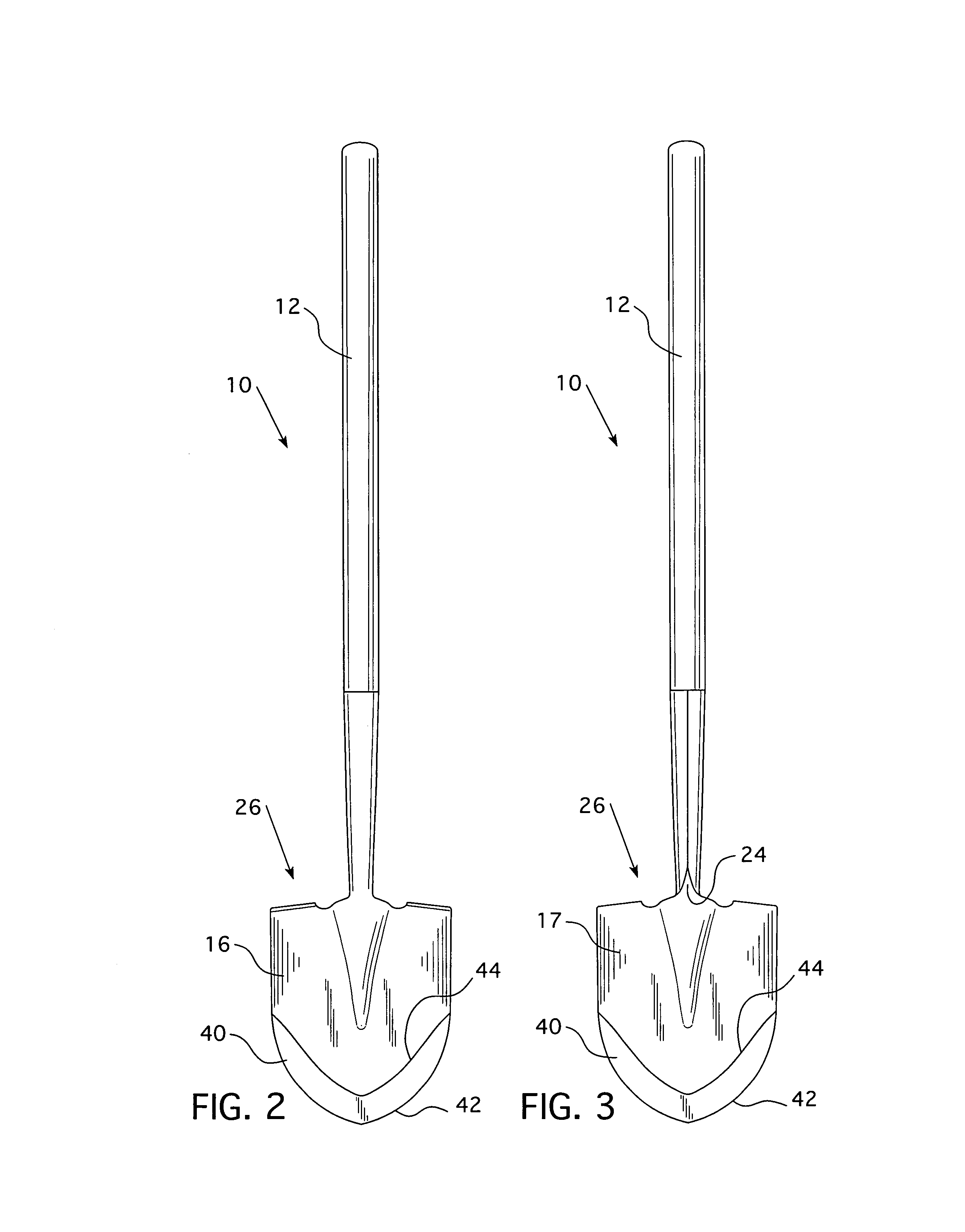
[0015]As shown in FIG. 1-7, a garden tool 10 includes an elongated handle 12 and a tool head 14. It is noted that the size of the handle 12 is adaptable to the purpose of the tool head 14. That is, as shown, the garden tool 10 is a full sized shovel wherein the handle 12 is about five feet long. It is understood that if the tool were a hand shovel (not shown), the handle 12 would be much shorter, typically about 6 inches long. As shown, the tool head 14 is a shovel, however, it is understood that the tool head 14 may be any type such as, but not limited to, scoops, spades, rakes, hoes, and scrapers. The tool head 14 has a body 15 with a front side 16, and back side 17 (FIG. 3), a leading edge 18, side edges 30, 32, a medial portion 20, and a rear edge 22. Each of the edges 18, 22, 30, 32 has a face 19, 23, 31 (FIG. 6), 33 (FIG. 4) respectively, that extends between the front side 16 and the back side 17. Typically, the tool head rear edge 22 includes a socket 24 structured to be cou...


PUM


Abstract

A garden tool wherein the leading edge of the tool head has a leading edge coated with a hardness enhancing material.

Description

BACKGROUND OF THE INVENTION[0001]1. Field of the Invention[0002]The disclosed concept relates to a garden tool head having a leading edge coated with a hardness enhancing material.[0003]2. Background Information[0004]Garden tools for manipulating soil are well known in the art. Tools such as, but not limited to, shovels, scoops, spades, rakes, hoes, and scrapers typically include an elongated handle and a metal tool head. The tool head includes a socket structured to be coupled to the handle and a body. The body may be generally flat, e.g., a spade, generally arcuate, e.g., a shovel, or include a bent or angled portion, e.g. a hoe. Further, the body may include a plurality of prongs structured to be inserted into the soil, e.g., a rake. Whatever the shape of the body, there is typically a leading edge opposite the socket that is structured to be inserted into the soil. Thus, the leading edge of the tool head typically is subjected to more wear and tear than the medial portion of the...

Claims


Application Information

Patent Timeline
Patent Type & Authority Applications(United States)
IPC IPC(8): A01B1/02A01B1/24
CPCA01B1/02A01B1/00
Inventor RANDOLPH, DAVID A.GROSS, JAMES M.
Owner IAMS
Learn More