
Flow regulator device

a flow regulator and flow regulator technology, applied in the direction of combustion process, working fluid for engines, lighting and heating apparatus, etc., can solve the problem of not always uniform distribution of clinker on the cooler gra

Inactive Publication Date: 2009-06-18
F L SMIDTH & CO AS
View PDF13 Cites 21 Cited by
  • Summary
  • Abstract
  • Description
  • Claims
  • Application Information

AI Technical Summary

Benefits of technology

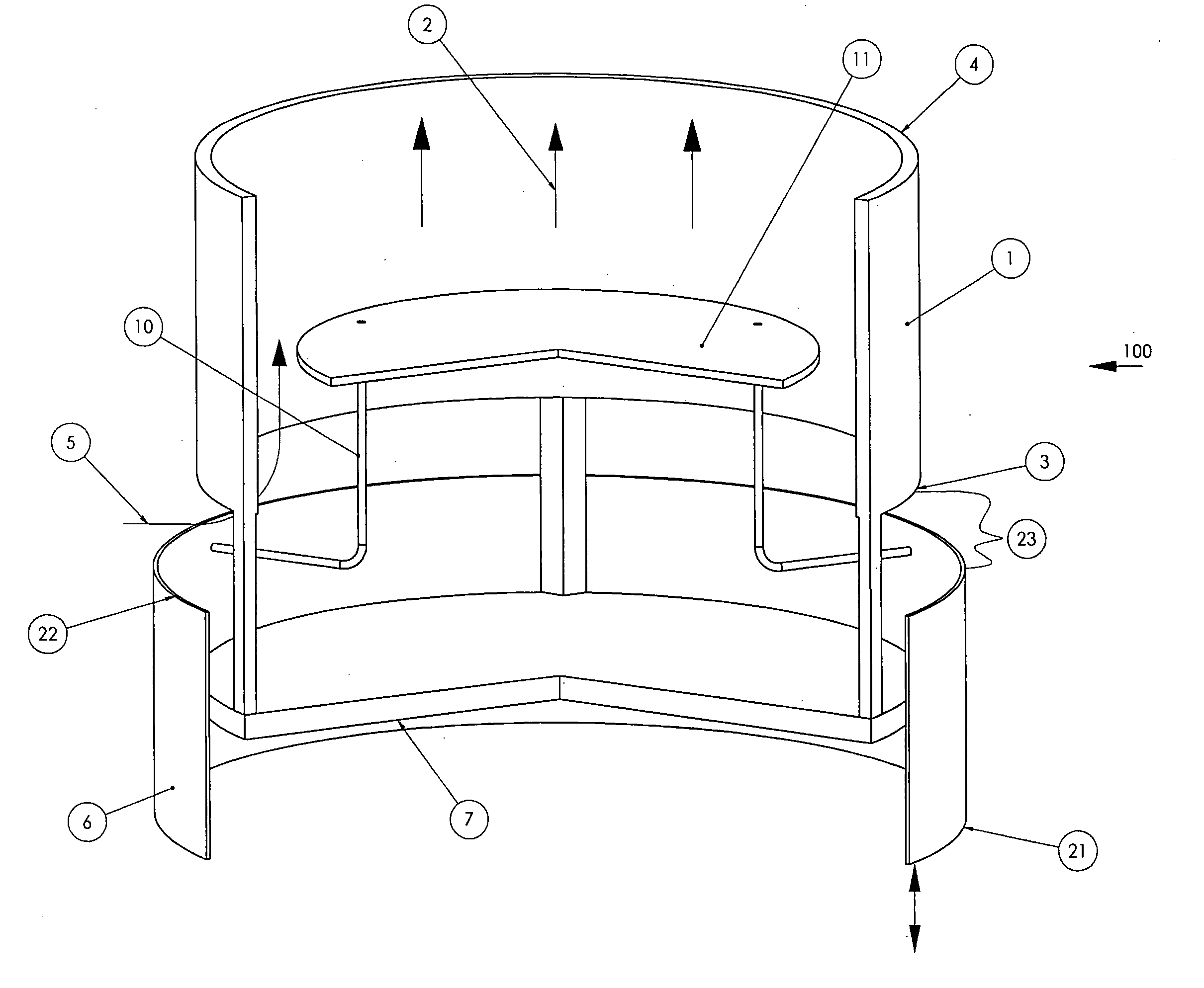
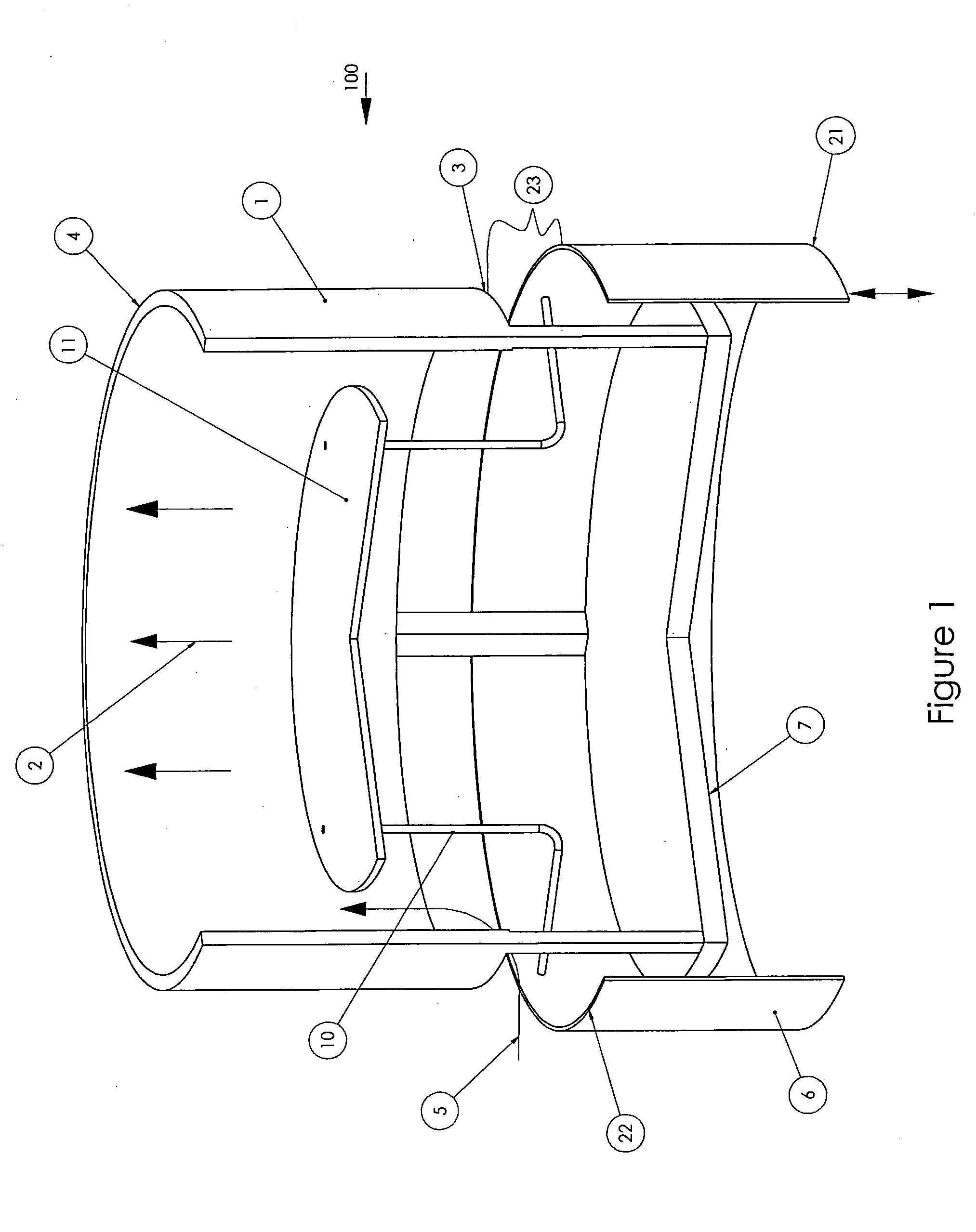
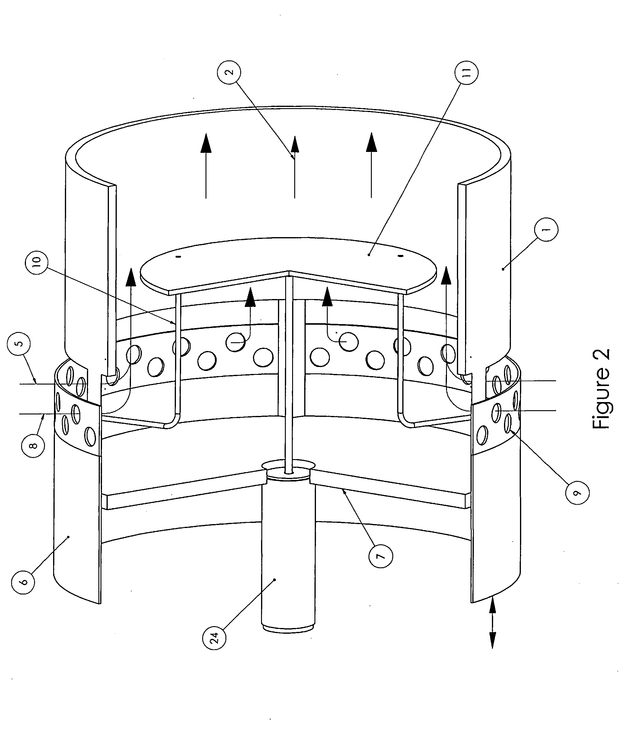
[0005]The above and other objects are realized by the fluid flow regulator of the present invention which comprises in combination a stationary hollow duct housing having a first end and a second end, being adaptable to have fluid flow therethrough between such ends. The device also incorporates a movable member aligned concentric with the duct having a forward end essentially similarly shaped and sized to the first end of the housing. The member may be spaced apart from the duct so that fluid can enter the duct housing through an opening defined by the space between the forward end of the member and the first end of the duct, with the member being movable relative to the duct to change the size of the opening between a first retracted position where the size of the opening is at a maximum, a second forward position where the size of the opening into the duct, is at a minimum or is closed, and all intermediate positions. The movement of the member is controlled by the movement of a float located within the duct. The position of the float, and accordingly the position of the member relative to the duct, can be preset by the operator of the invention to be responsive to process parameters such as pressure, temperature and / or the rate of fluid flow into the flow regulator. For example, when fluid flow into the duct is at a predetermined amount the float (and accordingly the member) can be preset to remain stationary, and the opening will remain at a predetermined size. When the fluid flow increases above such predetermined level (for instance, because the pressure drop across the duct and the material bed has decreased) the float will be moved in the direction of the fluid flow, the member will accordingly move toward the second position and the size of the opening suitable for fluid flow therethrough will be decreased. Likewise, when fluid flow into the duct is below said predetermined amount, the float will move the member toward the first position and the size of the opening suitable for fluid flow therethrough will be increased.

Problems solved by technology

In such a cooler the clinker is not always uniformly distributed on the cooler grate.

Method used


Image

  • Flow regulator device
  • Flow regulator device
  • Flow regulator device

Examples


Embodiment Construction

[0010]FIG. 1 illustrates one embodiment of the fluid flow regulator 100 of the present invention. Although fluid flow regulator 100 is at times described in the context of its use situated vertically in a clinker cooler, in which case the fluid flow is cooling air, the fluid flow regulator 100 can operate with any fluid and in other equipment and positions as described in part below.

[0011]Fluid flow regulator 100 comprises a hollow duct 1 (which, when used in a clinker cooler, is vertically situated) through which fluid is adapted to flow axially in the direction of arrows 2. Fluid enters the interior of duct 1 through the first end 3 generally at right angles to the longitudinal axis of duct 1 in the direction generally shown by arrow 5 and thereafter flows axially through the duct housing toward second end 4. Duct 1 can be made of any material that can withstand the intended application and is impenetrable to the fluid it is intended to convey. Second end 4 is adaptable to be plac...


PUM


Abstract

A fluid flow regulator of the present invention comprises in combination a stationary hollow duct housing having a first end and a second end through which fluid flows. The device also incorporates a movable member aligned concentric with the duct having an end essentially similarly shaped and sized to the first end of the housing. The member may be spaced apart from the duct so that fluid can enter the duct housing through an opening defined by the space between the end of the member and the first end of the duct, with the movement of the member serving to change the size of opening. The movement of the member is controlled by the movement of a float located within the duct. The position of the float can be preset by the operator of the invention so that when fluid flow into the duct is at a predetermined amount the float will remain stationary, and when the fluid flow increases above such predetermined level the float will be moved in the direction of the fluid flow and when fluid flow into the duct is below said predetermined amount, the float will move the member opposite the direction of fluid flow.

Description

BACKGROUND OF THE INVENTION[0001]The present invention relates to a flow regulator device that may be utilized in varied applications.[0002]In one application, the device of the present invention can be utilized in the process of cooling a bed of particulate material, such as cement clinker in a grate cooler, in which cooling gas from a source such as a fan is directed, via one or more ducts or channels, up through a gas distribution bottom that supports the bed of material to be treated and the bed of clinker material from one or more underlying compartments. In such a cooler the clinker is not always uniformly distributed on the cooler grate. Instead, the size and amount of the clinker to be cooled can be irregularly distributed on the cooler and the thickness of the clinker bed may exhibit variations both longitudinally and transversely through the cooler, which results in differing pressure drops through the clinker bed at different points throughout the cooler. Without a flow r...

Claims


Application Information

Patent Timeline
IPC IPC(8): F03B11/00
CPCF03B11/00F05B2210/16G05D23/015F23N3/007G05D7/0146Y02E10/226Y10T137/7782Y10T137/7834Y10T137/7785Y10T137/8593Y10T137/7792Y02E10/20
Inventor SALMENTO, JOHN S.
Owner F L SMIDTH & CO AS
Learn More