Battery charger cradle

a battery charger and cradle technology, applied in the field of battery charger cradles, can solve the problems of time-consuming and cumbersome setting the battery built-in device in place, the inability of the battery pack to be charged, and the difficulty of all users to always set the battery built-in device on the battery charger cradle in a normal manner, so as to achieve efficient detection, efficient charging, and wide area

Inactive Publication Date: 2009-06-18
SANYO ELECTRIC CO LTD
View PDF6 Cites 219 Cited by
  • Summary
  • Abstract
  • Description
  • Claims
  • Application Information

AI Technical Summary

Benefits of technology

[0007]Japanese Patent Laid-Open Publication No. H09-63655 (1997) presents a drawback that, when the battery pack on the battery charger cradle is out of alignment, the battery pack cannot be charged. This is because, when a relative position between the mobile electronic device and the battery charger cradle is out of alignment, the primary coil and the induction coil are not electromagnetically coupled to each other, and such state disables AC electric power to be carried from the primary coil to the induction coil. Such drawback can be remedied, as described in Japanese Utility Model Registration No. 3011829, when a positioning protrusion is provided to the battery charger cradle and also a positioning recess is provided to the mobile electronic device, with the positioning protrusion being fitted in the positioning recess. In such structure, the positioning protrusion is guided into the positioning recess, enabling a relative misalignment to be avoided between the mobile electronic device and the battery charger cradle.

Problems solved by technology

H09-63655 (1997) presents a drawback that, when the battery pack on the battery charger cradle is out of alignment, the battery pack cannot be charged.
The structure disclosed in Japanese Utility Model Registration No. 3011829, however, presents a drawback that it is time-consuming and cumbersome to set the battery built-in device in place because the battery built-in device is placed on the battery built-in device such that the positioning protrusion is guided into the positioning recess.
Another drawback presented in this structure is that it is difficult for all users to always set the battery built-in device on the battery charger cradle in a normal manner.
Even another drawback presented in such structure is that the battery built-in device cannot be made thin enough because the positioning recess is provided at a casing bottom and the induction coil is disposed superjacent to the positioning recess.
Since a battery built-in device such as a mobile phone is required to be made thinnest possible, an increased thickness caused by the positioning recess presents a drawback that convenient portability is spoiled.
This structure, however, also presents a drawback that efficiency decreases in the electricity to be carried from the primary coil to the induction coil because the magnetic field is also generated in a portion where the battery built-in device is not placed.
The structure also suffers the disadvantage that, when a metallic element such as iron is placed atop of the battery built-in device, heat is likely to be generated when an electric current flows to the metallic element by the effect of electromagnetic induction.

Method used


Image

  • Battery charger cradle
  • Battery charger cradle
  • Battery charger cradle

Examples


Embodiment Construction

)

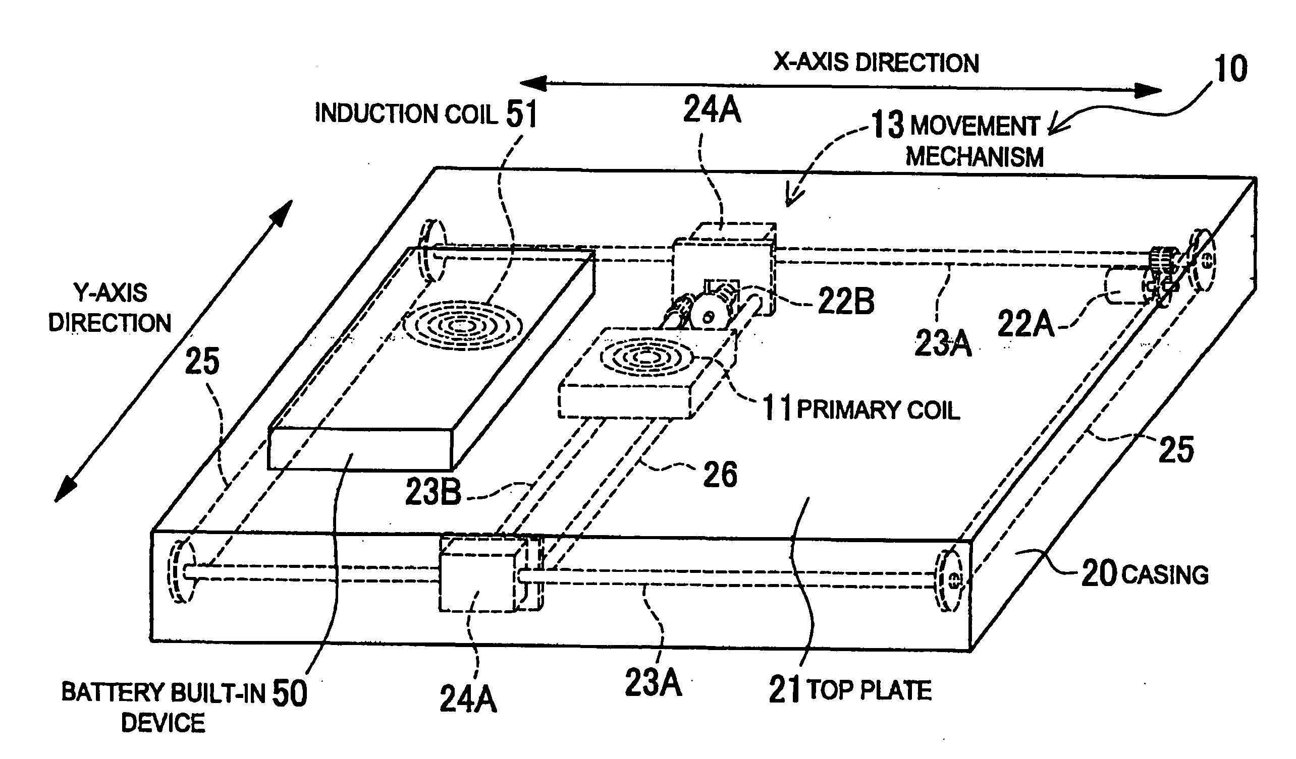
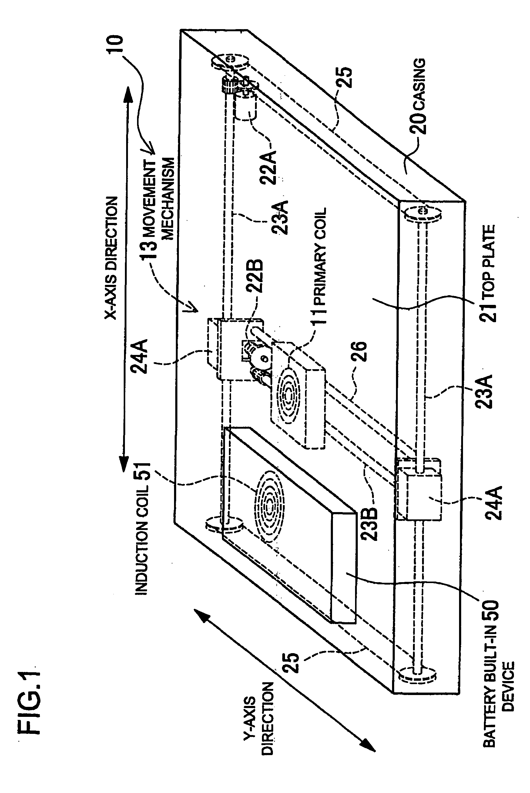
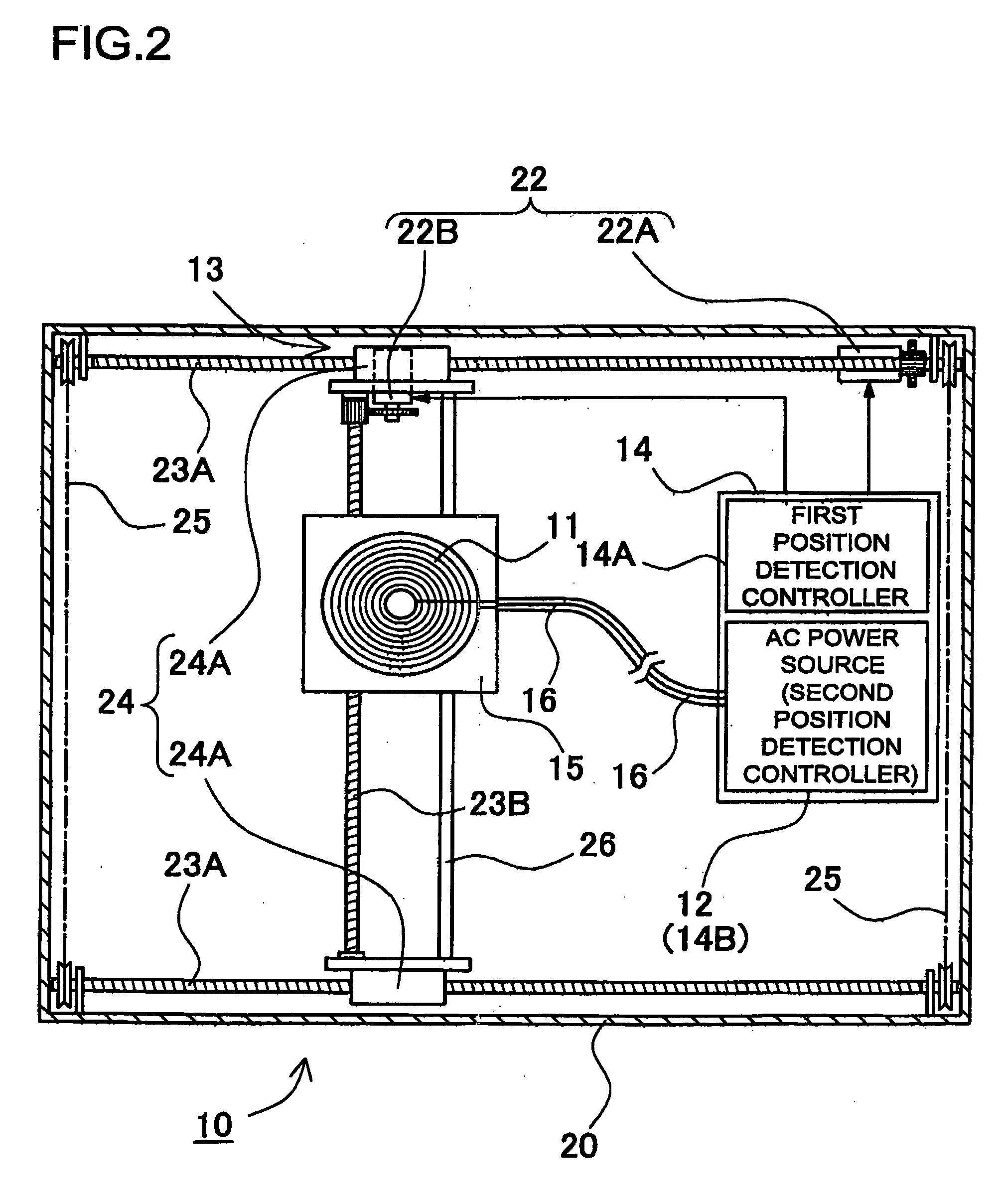
[0042]FIG. 1 through FIG. 6 show block schematic diagrams and principle diagrams of a battery charger cradle. As shown in FIG. 1 and FIG. 6, the battery charger cradle 10 is so designed as to place a battery built-in device 50 atop of the battery charger cradle 10 and charge a built-in battery 52 contained in a battery built-in device 50 by the effect of electromagnetic induction. The battery built-in device 50 incorporates an induction coil 51 electromagnetically coupled to a primary coil 11. The battery built-in device 50 contains a battery 52 that is charged by electric power induced to the induction coil 51. Instead, the battery built-in device 50 may be a battery pack.

[0043]FIG. 6 shows a circuit diagram of the battery built-in device 50. The battery built-in device 50 has a capacitor 53 being parallel-connected to the induction coil 51. The capacitor 53 and the induction coil 51 constitute a parallel resonance circuit 54. A resonance frequency of the capacitor 53 and the indu...


PUM


Abstract

In a battery charger cradle, a battery incorporated in a battery built-in device is charged by electric power induced to an induction coil. The cradle includes a primary coil inducing electromotive force to the induction coil, a casing having a top plate atop of which the battery built-in device is placed, a movement mechanism moving the primary coil along an inner surface of the top plate, and a position detection controller detecting a position of the battery built-in device placed on the top plate and controlling the movement mechanism to bring the primary coil closer to the induction coil in the battery built-in device. When the battery built-in device is placed on the top plate, the position detection controller detects the position of the battery built-in device, and the movement mechanism moves the primary coil to be brought closer to the induction coil in the battery built-in device.

Description

BACKGROUND OF THE INVENTION[0001]1. Field of the Invention[0002]The present invention relates to a battery charger cradle, on which battery built-in devices such as a battery pack and a mobile phone are placed, to recharge a built-in battery when electric power is carried by the effect of electromagnetic induction.[0003]2. Description of the Related Art[0004]There has been developed a battery charger cradle for recharging a built-in battery, where electric power is carried from a primary coil to an induction coil (a secondary coil) by the effect of electromagnetic induction. Refer to Japanese Patent Laid-Open Publication No. H09-63655 (1997) and Japanese Utility Model Registration No. 3011829.[0005]Described in Japanese Patent Laid-Open Publication No. H09-63655 (1997) is a structure that the primary coil excited by an AC power source is incorporated in the battery charger cradle and that the induction coil electromagnetically coupled to the primary coil is incorporated in a battery...

Claims


Application Information

Patent Timeline
Patent Type & Authority Applications(United States)
IPC IPC(8): H02J7/00
CPCH02J7/0045H02J7/025H02J50/10H02J50/90H02J7/0042H02J50/80H02J50/12H02J50/60
Inventor TOYA, SHOICHIMIZOGUCHI, YASUNARISATSUMA, EIJITERAO, KYOZO
Owner SANYO ELECTRIC CO LTD
Why Eureka
Try Eureka