Lighting device for operation panel and electronic device

a technology of electronic devices and operation panels, which is applied in the direction of illuminated signs, instruments, display means, etc., can solve the problems of increasing the cost of parts, difficult to uniformly light up the operation keys, and difficulty in using conventional lighting techniques to selectively light up the different display areas, etc., to achieve the effect of improving the operability and design of the electronic devi

Inactive Publication Date: 2009-06-18
CITIZEN ELECTRONICS CO LTD
View PDF6 Cites 16 Cited by
  • Summary
  • Abstract
  • Description
  • Claims
  • Application Information

AI Technical Summary

Benefits of technology

[0017]With this electronic device, the display areas can be displayed in a plurality o

Problems solved by technology

However, it has been difficult with the conventional lighting technique to selectively light up the different display areas, i.e. number and letter display areas, because the whole operation panel is illuminated from below with a single lightguide plate.
In this case, however, the nu

Method used


Image

  • Lighting device for operation panel and electronic device
  • Lighting device for operation panel and electronic device
  • Lighting device for operation panel and electronic device

Examples


first embodiment

[0024]a lighting device and an electronic device according to the present invention will be explained below with reference to FIGS. 1 to 3. It should be noted that the scale of the figures used in the following explanation is properly changed to show each constituent member in a recognizable size.

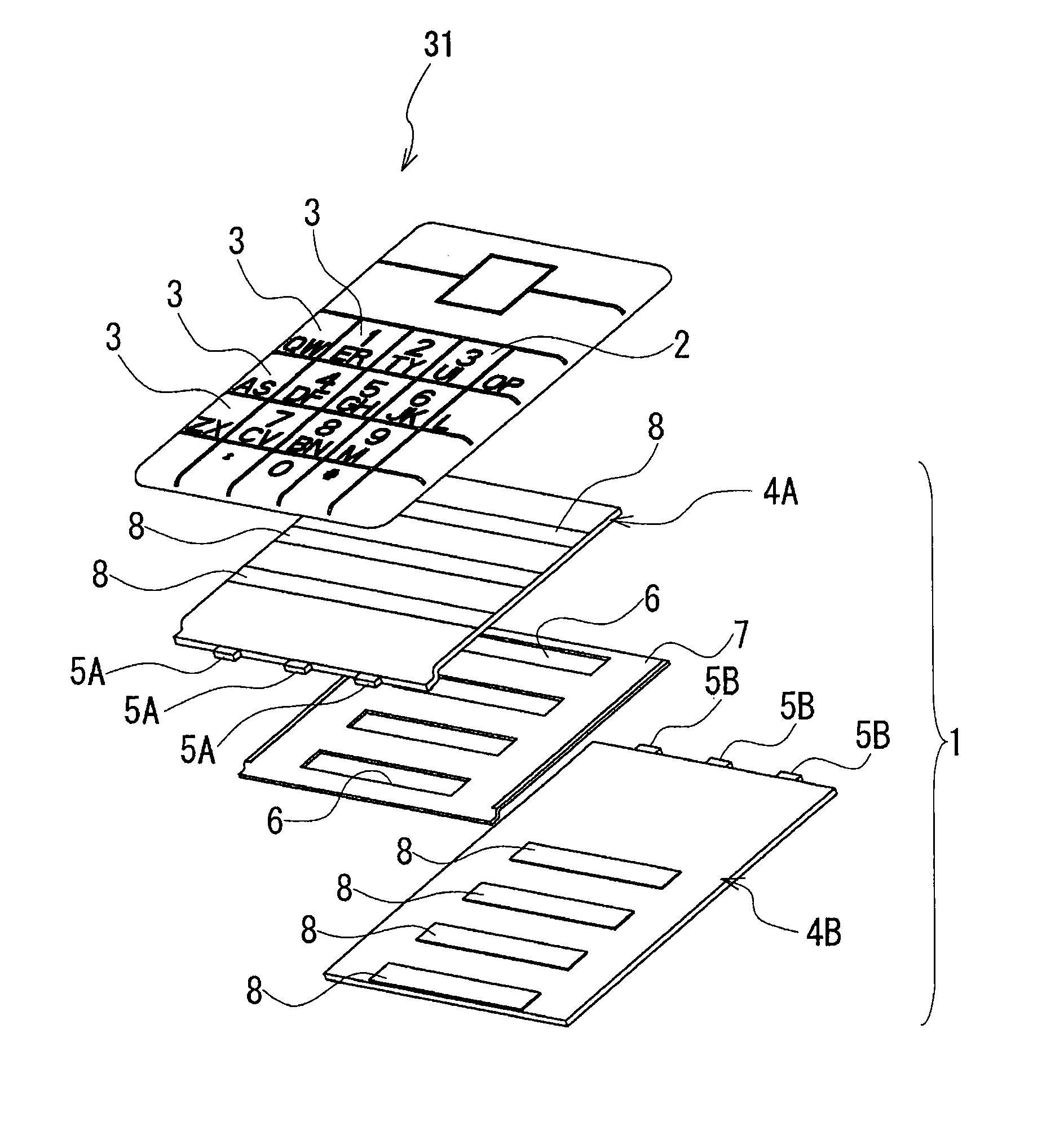
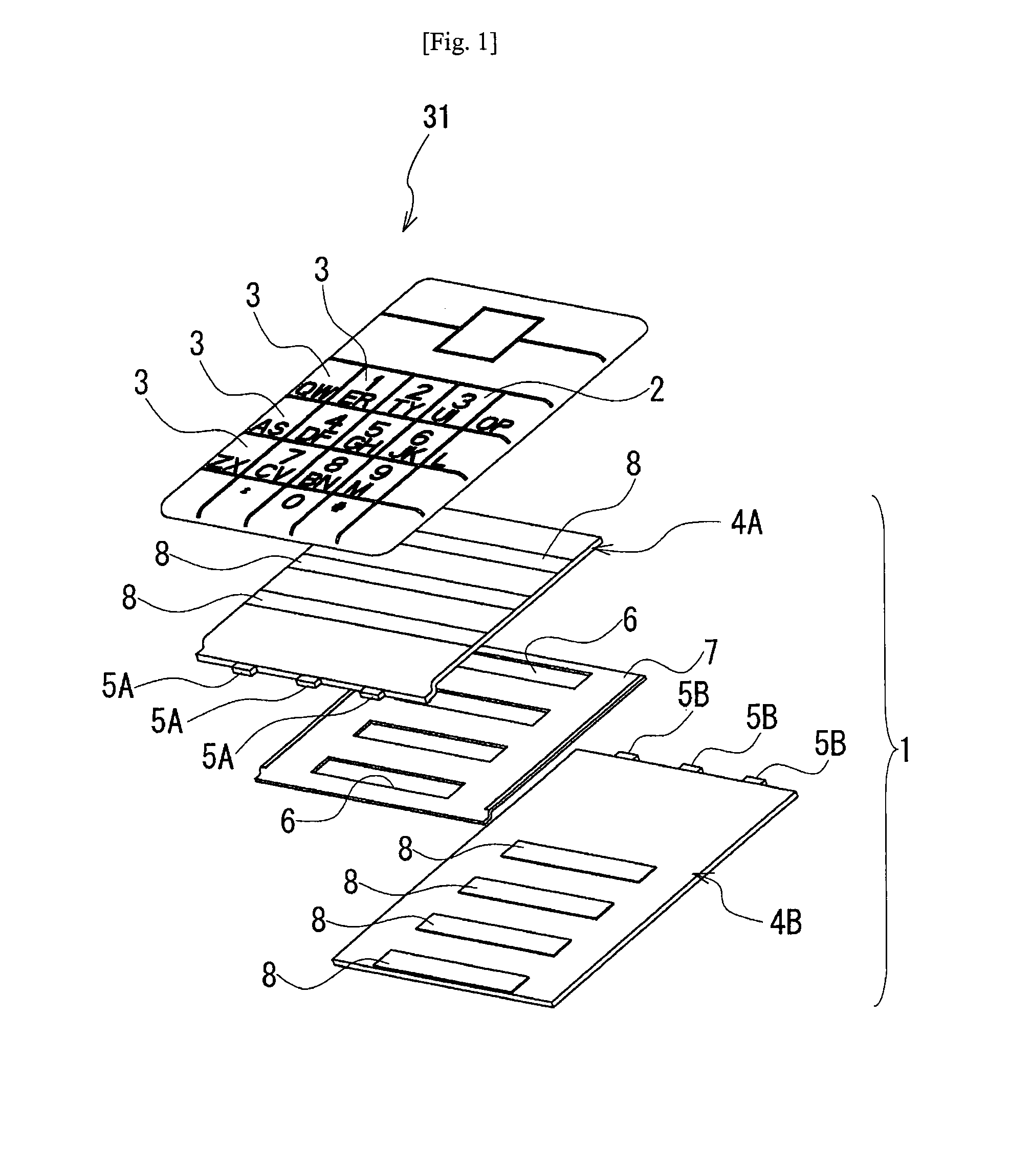
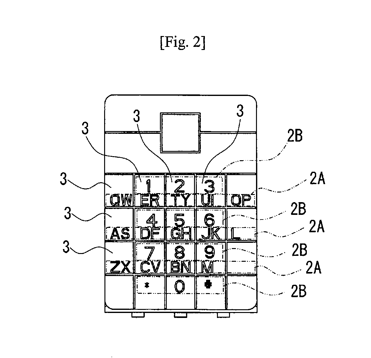
[0025]A lighting device 1 in this embodiment has, as shown in FIG. 1, an operation panel 31 having a plurality of operation keys 3, two sheet-shaped lightguide members 4A and 4B stacked at a back of the operation panel 31, light sources 5A and 5B arranged to face edges of the two sheet-shaped lightguide members 4A and 4B, respectively, and a sheet-shaped light shield member 7 disposed between the two sheet-shaped lightguide members 4A and 4B. In the illustrated example, the operation panel 31 is a single panel made of a synthetic resin or the like and has a plurality of operation keys formed thereon in a matrix. The operation panel 31 is, however, not limited to the illustrated structure bu...

second embodiment

[0040]As shown in FIGS. 5 and 6, a lighting device 21 comprises a stack of three sheet-shaped lightguide members 24R, 24G and 24B and two sheet-shaped light shield members 27, one of which is provided between the sheet-shaped lightguide members 24R and 24G. The other sheet-shaped light shield member 27 is provided between the sheet-shaped lightguide members 24G and 24B. The respective light sources of colors 25R, 25G, and 25B are arranged to face respective edges of the lightguide members 24R, 24G, and 24B.

[0041]The sheet-shaped lightguide members 24R, 24G and 24B have light-deflecting areas (light-scattering areas) 28R, 28G and 28B, respectively, which function in the same way as the sheet-shaped lightguide members in the first embodiment. In this embodiment, the operation keys on the operation panel each have a single display area. The operation keys include a red group 22R of operation keys that are illuminated with light deflected by the light-deflecting areas 28R of the sheet-...


PUM


Abstract

A lighting device illuminates an operation panel having a plurality of display area groups (2A, 2B) each including at least one display area. The lighting device can illuminate the operation panel with different light for each display area group. The lighting device includes at least two sheet-shaped lightguide members (4A, 4B) corresponding to the plurality of display area groups, respectively. The lightguide members are stacked at a back of the operation panel. The lighting device further includes light sources (5A, 5B) that are disposed to face at least one edge of the respective sheet-shaped lightguide members each guiding light from the respective light sources. The lightguide members (4A, 4B) have respective light-emitting areas (8) that deflect and emit the guided light toward the display areas of the corresponding groups (2A, 2B).

Description

RELATED APPLICATIONS[0001]This application claims priority under 35 U.S.C. §119 to Japanese Patent application No. JP2007-320881 filed on Dec. 12, 2007, the entire contents of which are hereby incorporated by reference.TECHNICAL FIELD[0002]The present invention relates to a lighting device used in an electronic device such as a mobile phone to illuminate its operation keys from the back thereof.RELATED ART[0003]A plurality of operation keys are used in electronic devices such as mobile phones, personal digital assistants (PDAs), mobile personal computers (PCs), and mobile game consoles. To facilitate key input operations in dark places, these electronic devices employ a lighting device for operation keys that illuminates the keys by applying light from the back thereof, for example.[0004]For example, Japanese Patent Application Publication No. 2001-167655 proposes a lighting device for pushbutton switches that includes a plurality of operation keys provided on a keypad or a key pane...

Claims


Application Information

Patent Timeline
IPC IPC(8): G09F13/04
CPCG06F3/0202G06F3/0238H01H13/83H04M1/23H01H2219/044H01H2219/062H04M1/22H01H2219/039
Inventor ISODA, HIROTOKUSANO, KENJIYAMADA, TATSURO
Owner CITIZEN ELECTRONICS CO LTD
Why Eureka
Try Eureka