Vehicular illumination lamp

a technology of illumination lamps and lamps, which is applied in the direction of lighting support devices, instruments, lighting and heating apparatus, etc., can solve the problems of not being able to effectively utilize the luminous flux of the light source, and achieve the effect of appropriate shap

Active Publication Date: 2009-06-18
KOITO MFG CO LTD
View PDF4 Cites 30 Cited by
  • Summary
  • Abstract
  • Description
  • Claims
  • Application Information

AI Technical Summary

Benefits of technology

[0009]By using the configuration of the vehicular illumination lamp described in “Patent Document 1” listed above, it is possible to make the lamp compact. In addition, by configuring the upper end edge of the shade included in the vehicular illumination lamp so as to have an appropriate shape, it is also possible to form a light distribution pattern that has the horizontal cut-off line and the oblique cut-off line in the upper end portion thereof.

Problems solved by technology

The vehicular illumination lamp described in “Patent Document 1,” however, has a problem in that it is not possible to effectively utilize the luminous flux from the light source because a part of the light directly emitted from the light emitting element is blocked by the shade.

Method used


Image

  • Vehicular illumination lamp
  • Vehicular illumination lamp
  • Vehicular illumination lamp

Examples


first embodiment

[0064]First, the present invention will be explained.

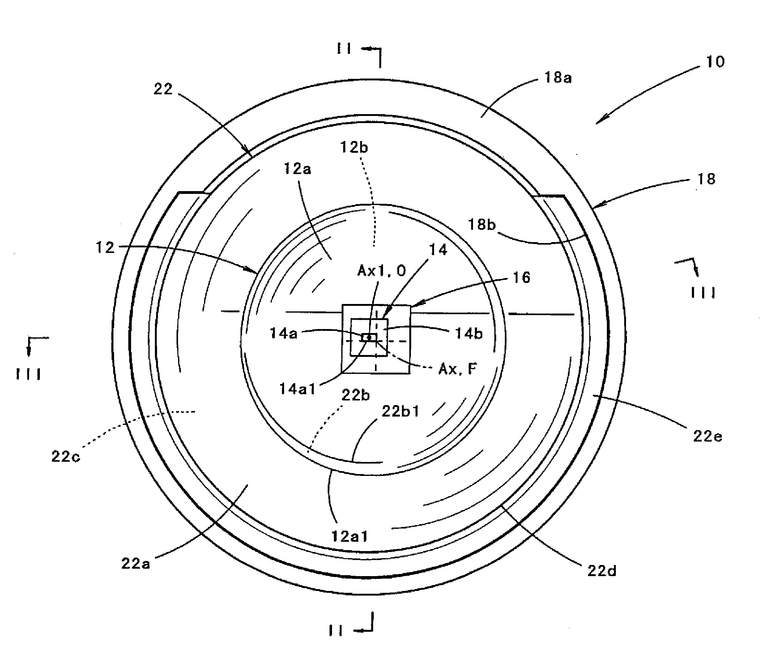
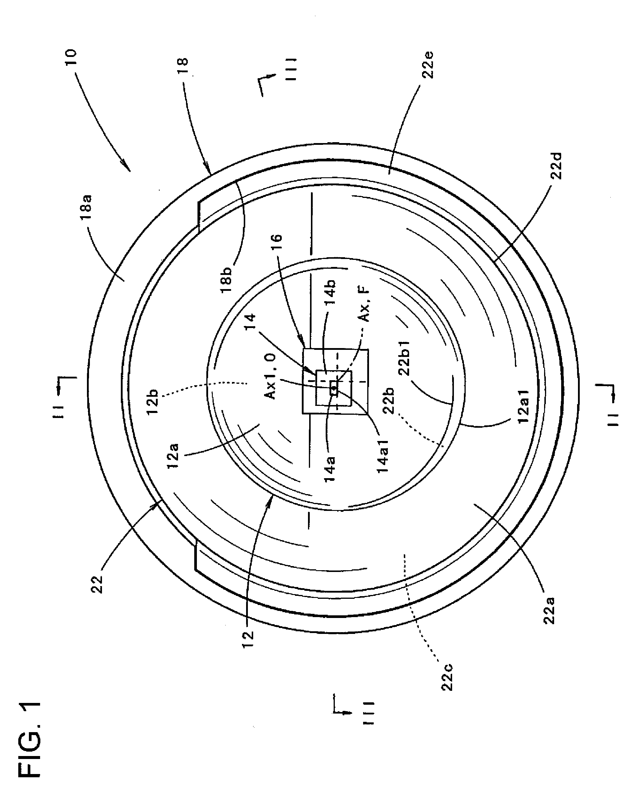
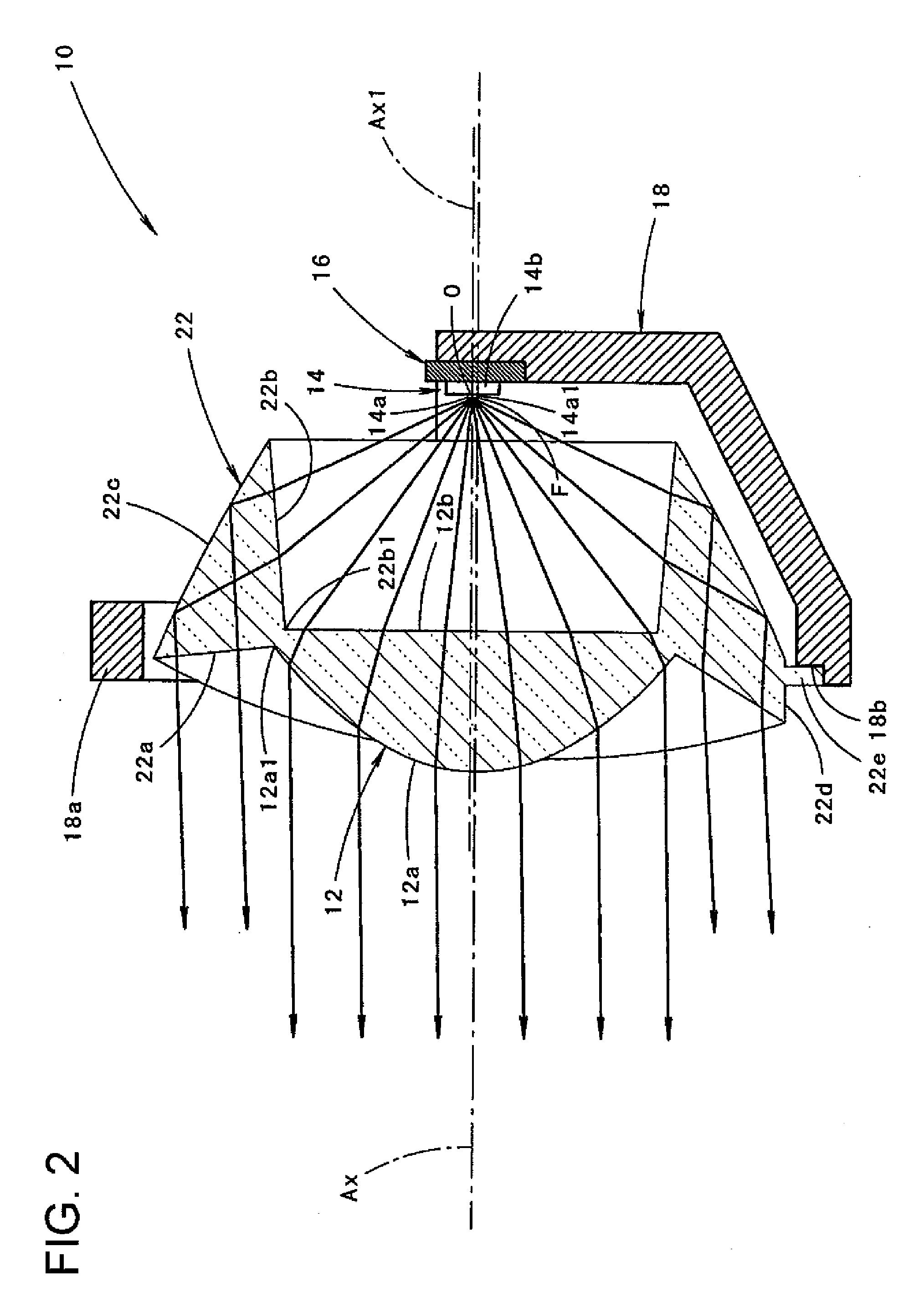
[0065]FIG. 1 is a front view that shows a vehicular illumination lamp 10 according to a first embodiment of the present invention. FIG. 2 is a cross-sectional view at the line II-II in FIG. 1. FIG. 3 is a cross-sectional view at the line III-III in FIG. 1.

[0066]As shown in these drawings, the vehicular illumination lamp 10 according to the present embodiment includes: a convex lens 12 positioned on an optical axis Ax extending in the vehicular longitudinal direction; an additional lens 22 that is integrally formed with the convex lens 12 in such a manner that the additional lens 22 surrounds the convex lens 12 in the manner of a band along the entire circumference thereof; a light emitting element 14 that is positioned in the proximity of a rear side focal point F of the convex lens 12; a metal plate 16 that supports the light emitting element 14; and a supporting member 18 that is made of metal and positions and supports the meta...

second embodiment

[0134]Next, the present invention will be explained.

[0135]FIG. 11 is a front view of a vehicular illumination lamp 110 according to a second embodiment of the present invention. FIG. 12 is a cross-sectional view at the line XII-XII in FIG. 11.

[0136]As shown in the drawings, the basic configuration of the vehicular illumination lamp 110 according to the present embodiment is the same as that of the vehicular illumination lamp 10 according to the first embodiment. However, the shape of the light emitting element 14 and the shape of a convex lens 112 are different from the examples according to the first embodiment. In accordance with these differences, the positional arrangement of the additional lens 22 is also different from the example according to the first embodiment.

[0137]In the vehicular illumination lamp 110 according to the present embodiment, the structure of the light emitting element 14 itself is the same as the example according to the first embodiment. However, the light...


PUM


Abstract

A vehicular illumination lamp includes a convex lens positioned on an optical axis in a vehicular longitudinal direction and a light emitting element positioned in a proximity of a rear side focal point of the convex lens. The vehicle lamp is configured so as to form a light distribution pattern that has a horizontal cut-off line and an oblique cut-off line in an upper end portion thereof by exercising deflection control, with a use of the convex lens, over light directly emitted from the light emitting element. The light emitting element includes a light emitting chip that has a rectangular light emitting surface. The light emitting element is positioned facing forward in such a manner that a lower end edge of the light emitting chip is positioned on a plane that includes the optical axis, while one of end points of the lower end edge is positioned on the rear side focal point. An additional lens is provided around the convex lens. The additional lens is integrally formed with the convex lens in such a manner that the additional lens surrounds the convex lens in a manner of a band. The additional lens includes an incident plane that is formed generally in a shape of a circular cylindrical plane centered on an axial line passing through a position in a proximity of a light emission center of the light emitting element and being parallel to the optical axis and that causes light emitted from the light emitting element to become incident to the additional lens in such a manner that the light is refracted into a direction that draws apart from the axial line; a reflecting plane that causes the light that has become incident from the incident plane to be internally reflected to a front; and an emission plane that causes the light that has been internally reflected on the reflecting plane to be emitted to the front as diffused light.

Description

BACKGROUND OF INVENTION[0001]1. Field of the Invention[0002]The present invention relates to a vehicular illumination lamp that uses a light emitting element as a light source. The present invention specifically relates to a vehicular illumination lamp that is configured so as to radiate light to form a light distribution pattern having a horizontal cut-off line and an oblique cut-off line in an upper end portion thereof.[0003]2. Related Art[0004]In recent years, light emitting elements such as light-emitting diodes have been used as light sources in vehicular illumination lamps.[0005]For example, “Patent Document 1” describes a vehicular illumination lamp that includes: a convex lens positioned on an optical axis extending in the front-back direction of the lamp; and a light emitting element positioned in the proximity of the rear side focal point of the convex lens. A so-called direct projection type of vehicular illumination lamp is configured so as to exercise deflection control...

Claims


Application Information

Patent Timeline
Patent Type & Authority Applications(United States)
IPC IPC(8): F21V7/00F21S8/10F21S8/12F21V5/00F21V13/00F21W101/10F21Y101/02H01L33/00H01L33/58H01L33/60
CPCF21S48/1154F21S48/1163F21S48/1233F21S48/1258F21S48/1275F21S48/1329G02B19/0028F21V5/08F21V7/0091F21W2101/10F21Y2101/02G02B19/0066F21V5/04F21Y2115/10F21S41/143F21S41/155F21S41/255F21S41/265F21S41/28F21S41/285F21S41/322F21W2102/155F21W2102/00
Inventor YAGI, TAKAYUKI
Owner KOITO MFG CO LTD
Why Eureka
Try Eureka