Fixing device, and image forming apparatus

A technology for fixing parts and components, which is applied in the direction of electric recording process applying charge pattern, equipment for electric recording process applying charge pattern, electric recording technique, etc., can solve problems such as difficulties and assembly problems, and achieve better assembly. , the effect of improving operability

Active Publication Date: 2012-07-04
RICOH KK
View PDF11 Cites 10 Cited by
  • Summary
  • Abstract
  • Description
  • Claims
  • Application Information

AI Technical Summary

Problems solved by technology

[0015] However, in the process of assembling several parts on the side of the fixing member such as the supporting member as an assembly, there is a problem of assemblability.
That is, since the support member is a thin metal tube, and its cross-section at least accommodates the clamping forming part, it is determined that it is not a simple circle, so the inner diameter of the axial end portion of the support member It is difficult to smoothly insert the cylindrical part of the flange part with a small clearance

Method used


Image

  • Fixing device, and image forming apparatus
  • Fixing device, and image forming apparatus
  • Fixing device, and image forming apparatus

Examples


Embodiment

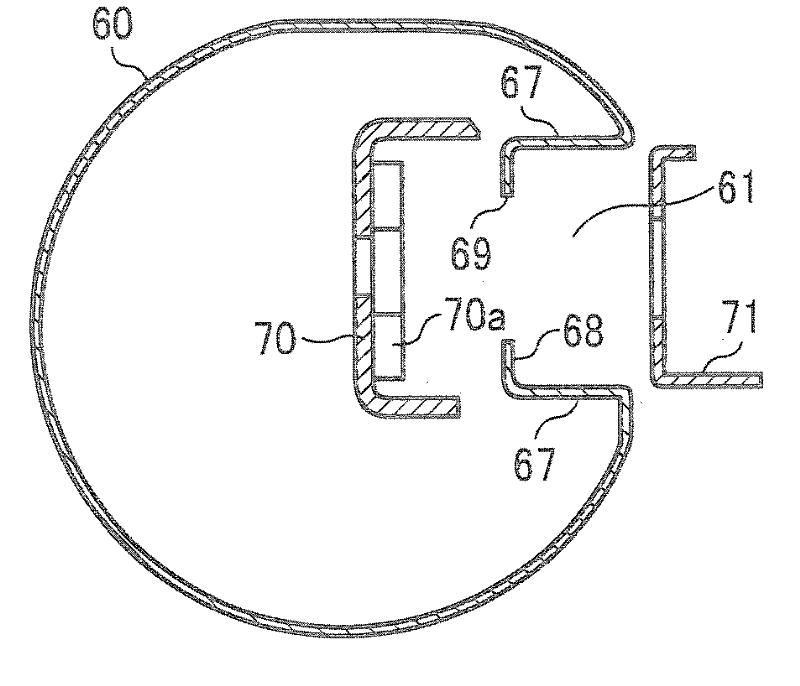
[0223] Under the same conditions as the above embodiment, using Figure 5 For the support member 60 of the size and shape shown, only the difference ( L2L1 ) between the outer peripheral length L1 of the supporting member 60 incorporating the nipping forming member 26 and the inner peripheral length L1 of the fixing belt 21 was changed, and various measurements were performed. Measurements were performed on the relationship between the difference in peripheral length and the surface temperature of the supporting member 60 , and the difference in peripheral length and the frictional force between the supporting member 60 and the fixing belt 21 .

[0224] Figure 11 Indicates its result. Such as Figure 11As shown, when the circumference difference exceeds 0.9 mm, the surface temperature of the supporting member 60 exceeds the prescribed temperature limit value. That is, when the difference in circumference exceeds 0.9 mm, since the fixing belt 21 is loosely wound around the ...


PUM


Abstract

The invention provides a fixing device and an image forming apparatus capable of maintaining the shape of the cross section of a holder and meanwhile improving the assembly. The fixing device comprises a fixing belt, a pressure roller which is in compression joint with the outer periphery of the fixing belt and is fixedly arranged inside the fixing belt, a holder with the outer periphery thereof being slidingly contacted with the inner periphery of the fixing belt, a heater for heating the holder, a tubular portion (28a) for maintaining the shape of the portion adjacent to the end of the holder through the internal part that is inserted in the axial end of the holder, and a flange (28b) fixedly arranged in a frame of fixing device, so as to mount and dismount a flange component (28) in the frame of the fixing device in such a manner to maintain the holder. In a portion of the flange component (28) on the periphery of the tubular portion (28a), inclined surfaces (28d1, 28d2) which are extended in the axial direction of the tubular portion (28a) and are inclined towards the tubular center along with the axial distal end at the outer peripheral side of the tubular portion (28a) are arranged, and a guide portion (28d) which is slidingly contacted with the inner peripheral portion of the holder and then is guided onto the outer periphery of the tubular portion (28a) when inserted into the internal part of the axial end of the holder is arranged.

Description

technical field [0001] The present invention relates to a fixing device for fixing toner to a recording medium by heat and pressure, and a FAX (facsimile machine), printer, copying machine, and multifunction machine using an electrophotographic method, an electrostatic recording method, or the like using the fixing device and other image forming devices. Background technique [0002] Conventionally, as image forming apparatuses such as copiers and printers, various image forming apparatuses using electrophotography are generally considered. The image forming process is to form an electrostatic latent image on the surface of the photoreceptor drum of the image carrier, and to visualize the electrostatic latent image on the photoreceptor drum by developing the toner of the developer, etc. Then, the developed image is transferred to recording paper by a transfer device, and the image is placed on it, and the toner image on the recording paper is fixed by a fixing device using ...

Claims


Application Information

Patent Timeline
Patent Type & Authority Applications(China)
IPC IPC(8): G03G15/20G03G15/00
CPCG03G15/2053G03G2215/2035
Inventor 山口嘉纪吉川政昭石井贤治荒井裕司高木启正岩谷直毅德田哲生池渊丰瀬下卓弥今田高广藤本一平吉永洋后藤创吉浦有信下川俊彦
Owner RICOH KK
Why Eureka
Try Eureka