Apical cutting thread dental implant

a technology of dental implants and cutting threads, applied in dentistry, dental surgery, medical science, etc., can solve the problems of difficult evacuation of cavities, severe and lasting damage to nerves, tissue and bone, and still possible, so as to minimize the risk of complications, enhance stability, and eliminate drawbacks

Inactive Publication Date: 2012-07-26
HOLMES DAVID LC
View PDF5 Cites 9 Cited by
  • Summary
  • Abstract
  • Description
  • Claims
  • Application Information

AI Technical Summary

Benefits of technology

[0010]The present invention is directed to eliminating the drawbacks inherent in the prior art by providing a surgical implant for dental applications wherein the implant is cylindrically shaped and configured to have exterior and interior threading designed to enhance stability and minimize the risk of complications due to bone compression and damage when the implant is secured to the bone tissue.

Problems solved by technology

Even when performed by expert practitioners, it is still possible for severe and lasting damage to be done to nerves, tissue and bone during an implant procedure.
Furthermore, in spite of the use of calibrated measurements to ensure an implant will fit properly, it is difficult to evacuate a cavity such that the dimensions perfectly confirm to the implant.
As a result, prior art implants suffer from poor stabilization, fitting or immobilization issues.
These issues can lead to failure of the implant, or unnecessary further dental or surgical intervention.
However, despite the presence in the prior art of implants with self-tapping screws threads that are used in pre-drilled cavities, there is a tendency for the bone chips to be caught between the implant threads and the walls of the cavity, which compression of the wall area that can cause the implant to fail.
This can, and does result in damage to bone cells.
If irreparable damage is done to the jawbone, osteonecrosis can result.
Additionally, even when wielded by expert practitioners, the operation to place an implant can be complex and difficult.
However, the threads of the Linkow implant do not extend to the apical end of the implant and thus do not provide a mechanical anchor for the implant in that area.
Thus, securing it in place may cause the cavity to punch through jawbones lacking in sufficient vertical bone height.
Thus, it has stability issues surrounding implant to bone contact (not sure if this sentence adds anything).
Aldecoa fails to provide an internal chamber in the implant allowing for the shepherding of bone shavings into such a space during the securing procedure.
In addition, once the bone has integrated around this implant design, the resistance to vertical forces in this apical area and thus implant stability is reduced due to the reduced apical threads.
However, like the Guedj implant, the Galvan implant is rather long and like the Aldecoa implant it fails to provide an interior cavity to contain bone shavings.
Primarily, the cited prior art references still fail to adequately provide for a dental implant with a reduced profile to accommodate patients with narrow jawbones (lacking in sufficient vertical bone height).

Method used


Image

  • Apical cutting thread dental implant
  • Apical cutting thread dental implant
  • Apical cutting thread dental implant

Examples


Embodiment Construction

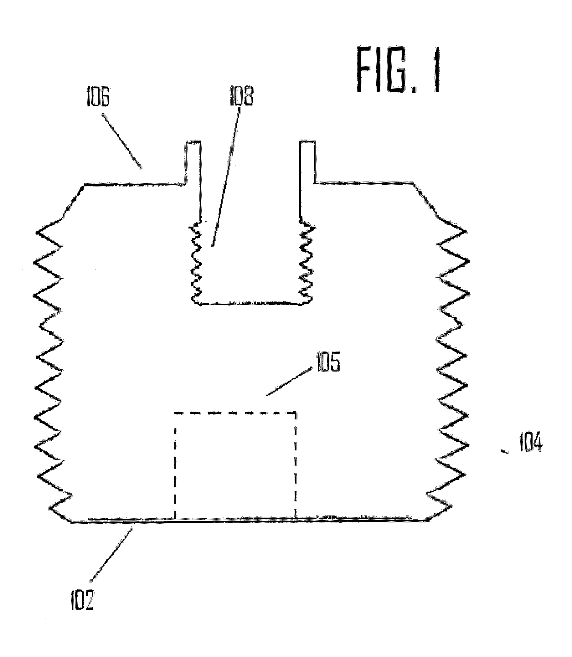
[0022]As seen in FIG. 1, a traditional dental implant as provided in the prior art is illustrated. The prior art dental implant has a roughly cylindrical shape designed to fit within a corresponding hole drilled into a portion of a patient's jawbone. A traditional implant possess an apical end 102 that is substantially flat and is designed to maximize contact between the apical end 102 of the implant and the bottom portion of the pre-drilled cavity in the jawbone. In order to assist in the stability of the prior art implant, exterior threads 104 are provided on the exterior of the implant so as to cut and thread their way into the sides of the pre-drilled cavity. Some prior implants contain an interior cavity 105 in which bone chips created by the threading operation may be stored. Furthermore, the implant possesses a coronal end 106 which is adapted to secure an abutment or crown attachment by means of a threaded recess 108 or other securing mechanism.

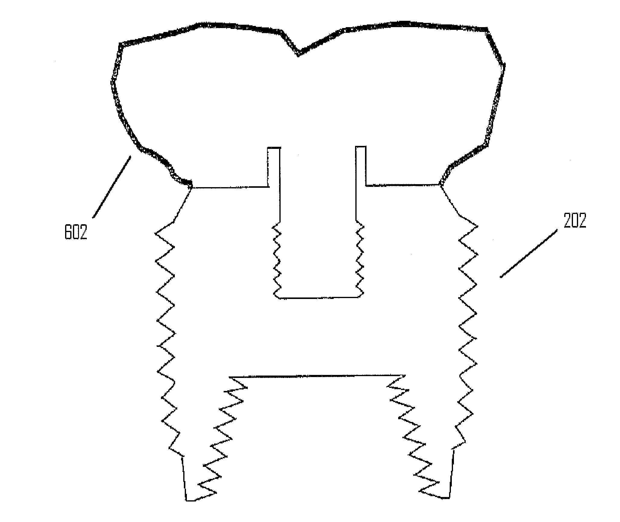
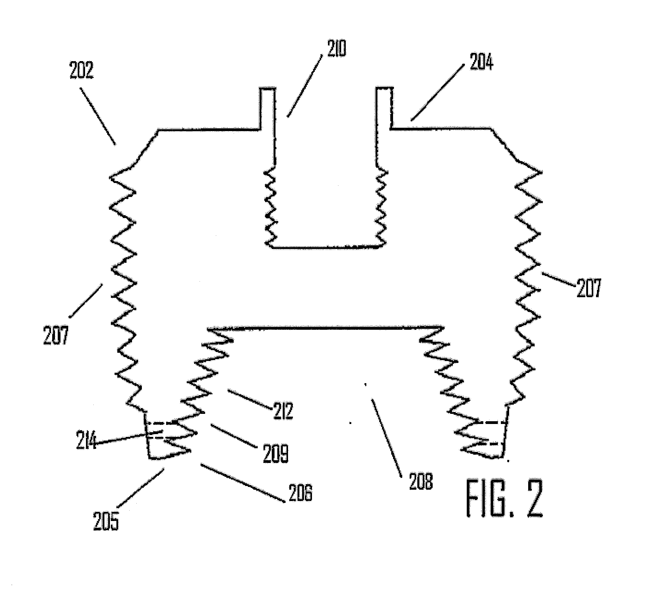
[0023]As seen in FIG. 2, an em...


PUM


Abstract

An endo-osseous implant has a roughly cylindrical shape with a threaded exterior surface and an internal cavity at the apical end. The internal cavity is open toward the apical end and it has threaded walls that taper toward the exterior surface of the implant to form an apical cutting edge where they meet the threads of the outer surface. A drill shorter in length than the implant, is used to form an osseous cavity in which the longer implant is secured. The implant threads may be self-taping. As a result, upon securing the implant to the osseous tissue, bone fragments and shavings are directed into the internal cavity. When the implant reaches the base of the cavity the cutting edge cuts into the base and further anchors the implant in place.

Description

BACKGROUND OF THE INVENTION[0001]This invention relates to dental implants and, more particularly, to apical end modified dental implants for improved patient safety during surgical procedures, wherein osteotomy preparation (removal by drilling) of the bone is minimized to avoid permanent or temporary injury, including paraesthesia, and implant interlocking and mechanical / biological stability in the bone is maximized through increased implant-bone surface area, and mechanical stability.[0002]It is common in the field of dental implants to use traditional drills and procedures to insert dental implants into the jawbone. In the field of the invention, it is standard procedure to effect the placement of implants by drilling or otherwise generating a sufficient cavity or bore within a patient's jawbone. The resulting cavity is configured in order to accept the insertion of a dental implant that is threaded or otherwise capable of being secured within the cavity. Therefore, the cavity in...

Claims


Application Information

Patent Timeline
Patent Type & Authority Applications(United States)
IPC IPC(8): A61C8/00
CPCA61C8/0039A61C8/0022
Inventor HOLMES, DAVID LC
Owner HOLMES DAVID LC
Why Eureka
Try Eureka