Wavelength dispersive device with temperature compensation

a dispersed image and temperature compensation technology, applied in the field of optical dispersive devices, can solve the problems of compromising the imaging properties of the optical system, difficult or impossible, and the shift of the dispersed image at the focal surfa

Active Publication Date: 2009-06-18
LUMENTUM OPERATIONS LLC
View PDF8 Cites 22 Cited by
  • Summary
  • Abstract
  • Description
  • Claims
  • Application Information

AI Technical Summary

Benefits of technology

[0017]According to one aspect of the invention, the apex angle of the first wedged prism is such that the first wedged prism is effective to cause the first angles to vary with the tempera

Problems solved by technology

However, as the temperature of the optical system of the WDD changes, the optical beam path through the WDD may vary, resulting in shifts of the dispersed images at the focal surface.
In practice however, this is often difficult or impossible, as materials with r

Method used


Image

  • Wavelength dispersive device with temperature compensation
  • Wavelength dispersive device with temperature compensation
  • Wavelength dispersive device with temperature compensation

Examples


Embodiment Construction

[0034]Embodiments of the invention are illustrated in FIGS. 3, 9, and 13, with selected constituent elements and sub-systems shown in FIGS. 4-7, and 11 in various embodiments thereof. In all these figures, like reference labels are used to identify like elements. In some figures, axes of a same Cartesian coordinate system (x,y,z) may be shown to illustrate spatial relationships between views represented in different figures.

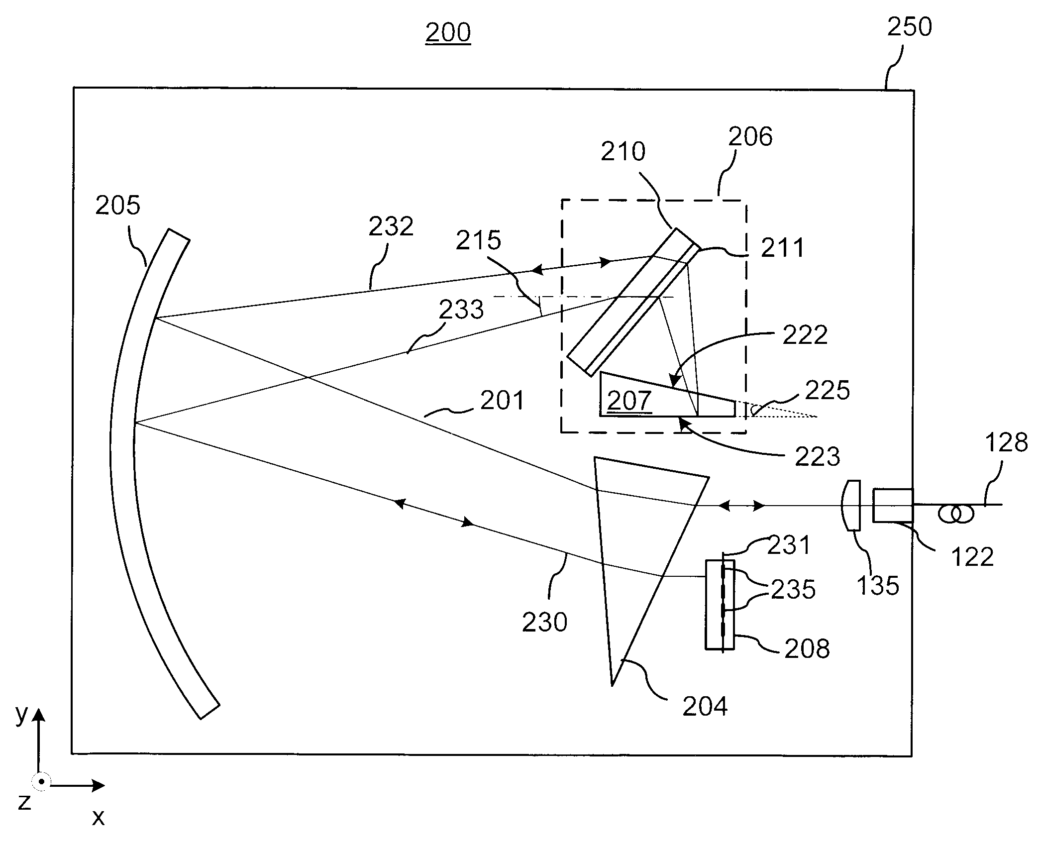
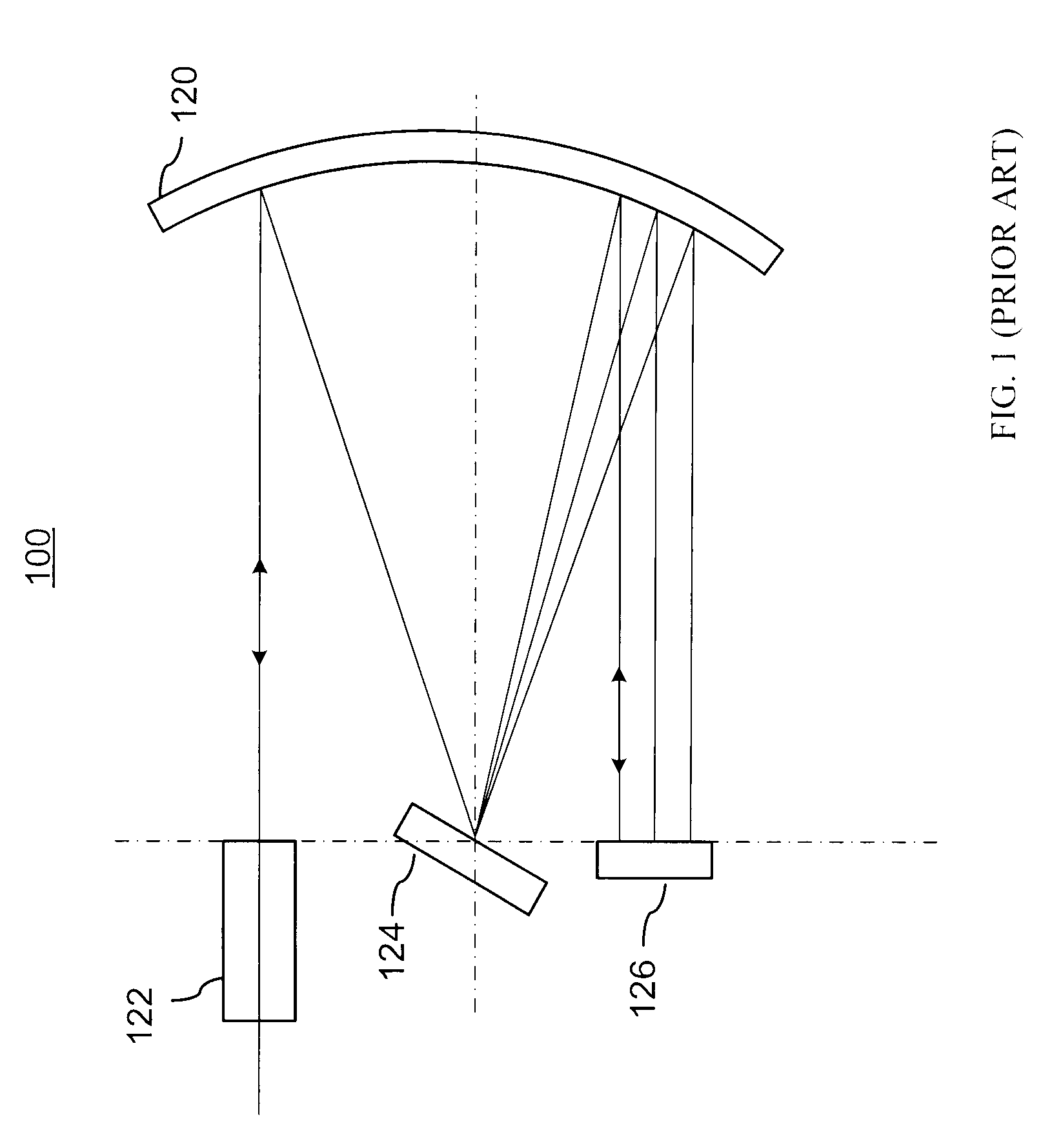
[0035]FIG. 3 illustrates an improved wavelength dispersive device (WDD) 200 incorporating elements of the present invention, which in its different embodiments may operate as a WSS, a DGE, a WB, or a spectrometer. The WDD 200 is generally based on a WDD platform 100 that is illustrated in FIG. 1 and described in U.S. Pat. No. 6,707,959 to Ducellier et al, which is assigned to the assignee of the instant application and is incorporated herein by reference.

[0036]The WDD 200 includes a light redirecting element having optical power in the form of a concave, for exam...


PUM


Abstract

The invention relates to fiber-optic wavelength dispersive devices incorporating a wavelength dispersive reflector that provides auto-compensation of variations of output spectral characteristic with temperature and includes a transmissive dispersion that is followed by a beam-folding reflecting surface in a double-pass configuration grating and is coupled to a wedged shaped prism.

Description

CROSS-REFERENCE TO RELATED APPLICATIONS[0001]The present invention claims priority from U.S. Provisional Patent Application No. 61 / 006,011 filed Dec. 14, 2007, entitled “Dispersive subsystem producing a pre-determined non-zero shift in diffracted angle with temperature”, which is incorporated herein by reference.TECHNICAL FIELD[0002]The present invention relates to optical dispersive devices incorporating diffraction gratings, and in particular to compensation of temperature-related shifts in such devices.BACKGROUND OF THE INVENTION[0003]Optical wavelength dispersive devices (WDD) often use diffraction gratings to spatially disperse different wavelength of incoming light and direct them along differing optical paths. Such grating-based WDD typically also includes an input aperture to launch light into the device, and collimating or focusing optical elements having optical power such as lenses and curved mirrors to form spectrally dispersed images on a focal surface.[0004]One common ...

Claims


Application Information

Patent Timeline
IPC IPC(8): G02B6/34
CPCG02B6/29398G02B6/29311
Inventor MCLAUGHLIN, SHELDONMURLEY, CHESTER
Owner LUMENTUM OPERATIONS LLC
Why Eureka
Try Eureka