
Pivoting conveyor including a holding mechanism configurable for holding the conveyor in multiple positions

Inactive Publication Date: 2009-06-18
CNH IND AMERICA LLC
View PDF16 Cites 3 Cited by
  • Summary
  • Abstract
  • Description
  • Claims
  • Application Information

AI Technical Summary

Benefits of technology

[0005]What is disclosed is a pivoting conveyor and an associated holding mechanism for supporting the conveyor, which provides the ability to easily and conveniently lower and raise the conveyor, and secure or hold it in both the lowered and raised positions, for instance, when lowered, to prevent the conveyor from bouncing when traveling over rough roads or fields, and possibly damaging adjacent apparatus or the conveyor itself.
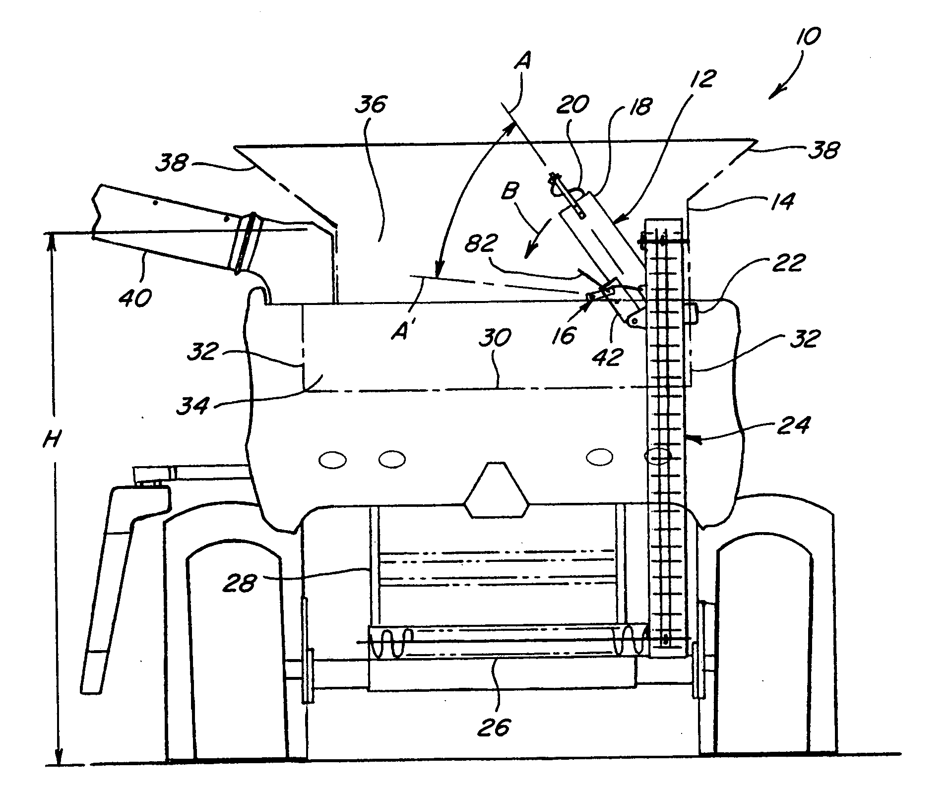
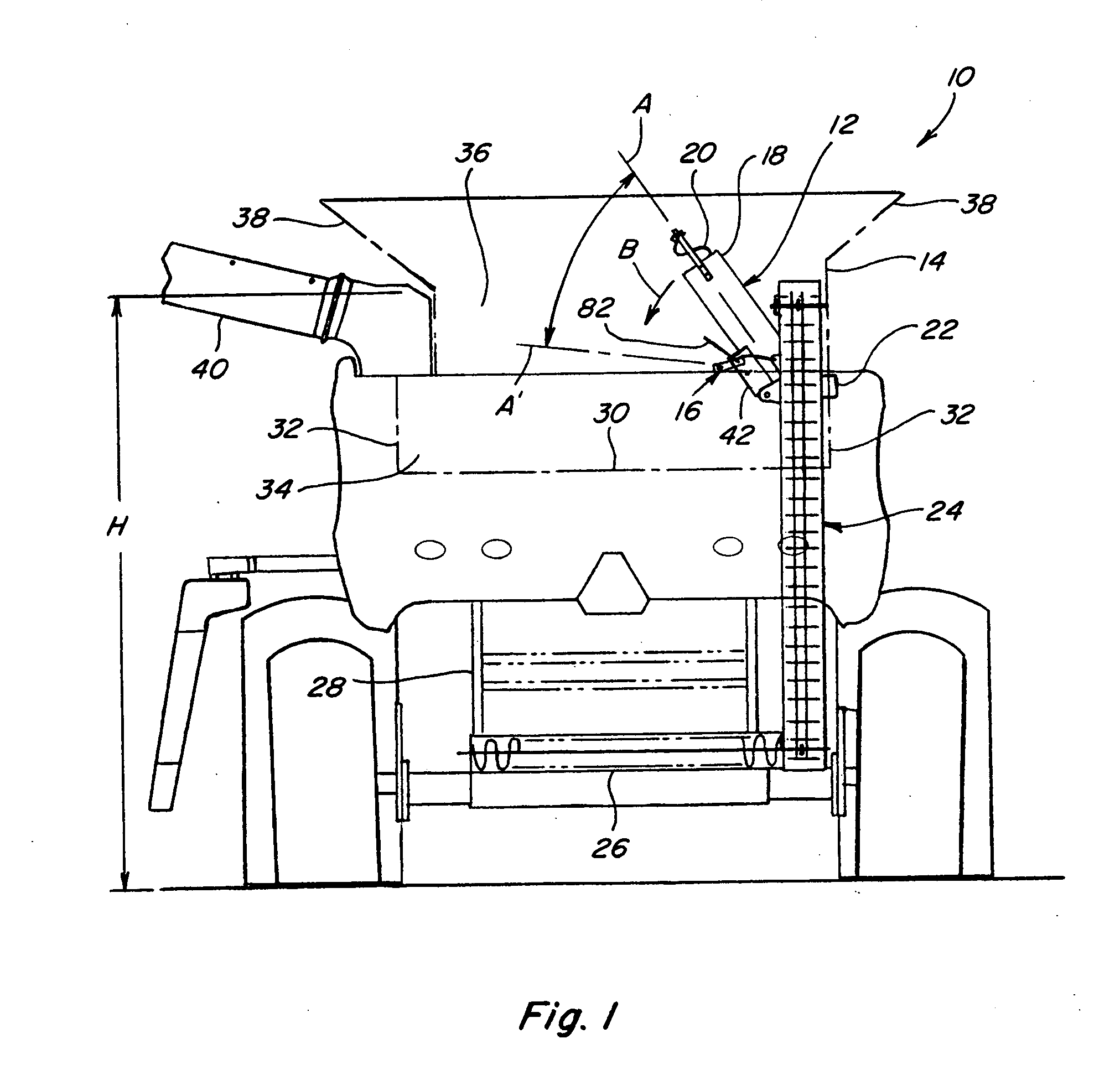
[0008]According to another preferred aspect of the invention, the conveyor comprises a grain delivery conveyor, and the first position corresponds to a lowered or stored position in a grain tank, wherein the conveyor is located in a lower region of the tank so as to extend upwardly only to about an upper edge or less of the tank, and the second position corresponds to a raised or deployed position, extending to an upper region of the tank, or to a region defined by grain tank extensions, so as to be operable for discharging grain into the upper region. As a result, in the lowered position the conveyor height is sufficiently low so as to provide adequate height clearance for transport and passage through doorways of buildings and under bridges, and in the raised position, the conveyor is of adequate height for depositing grain onto existing grain in the upper region of the tank, including when grain tank extensions are used to increase the grain capacity of the tank.
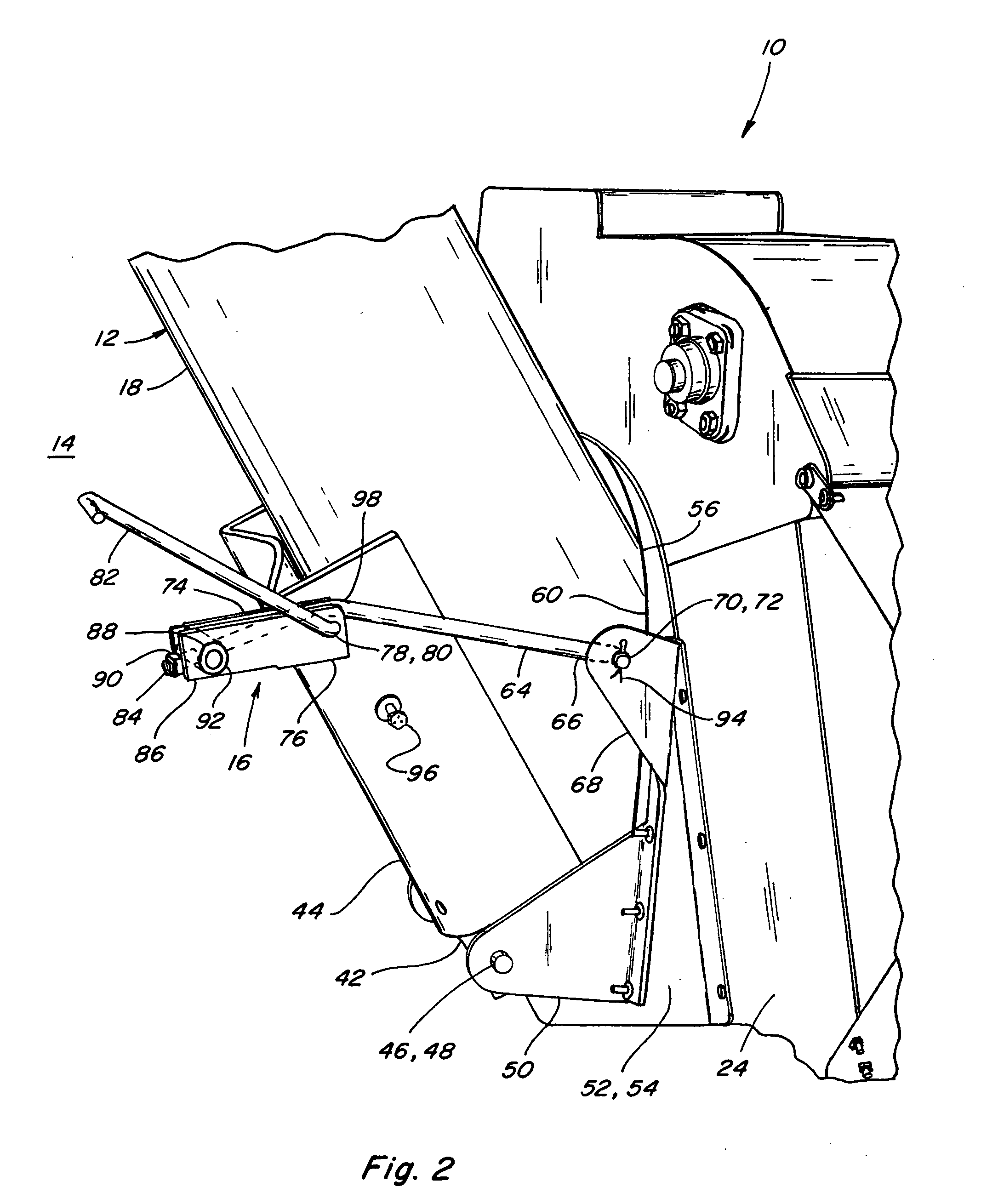
[0009]According to another preferred aspect of the invention, the mechanism includes a handle, preferably on or in connection with the second link and conveniently located, which handle can be grasped by a person using only one hand, for easily pivoting the holding mechanism between its different configurations for holding the conveyor in its different positions, and easily releasing the mechanism and conveyor for movement to the other position.

Problems solved by technology

However, some grain tank extensions make the overall height of the harvesting machine too great to allow the machine to be moved through doorways, or carried on a trailer over public roads.
As an additional concern, if the conveyor is lowered, and is not secured in position, and thus is movable in some manner, it is foreseen that travel by the machine over rough surfaces could generate movements of the conveyor, such as bouncing movements, that could cause damage the conveyor, and / or adjacent apparatus.

Method used


Image

  • Pivoting conveyor including a holding mechanism configurable for holding the conveyor in multiple positions
  • Pivoting conveyor including a holding mechanism configurable for holding the conveyor in multiple positions
  • Pivoting conveyor including a holding mechanism configurable for holding the conveyor in multiple positions

Examples


Embodiment Construction

[0017]Referring now the drawings, in FIGS. 1 and 2, a representative agricultural harvesting machine 10 is shown, including a grain delivery conveyor 12 supported and held in a raised deployed position within a grain tank 14 of machine 10, by a holding mechanism 16 constructed and operable according to the teachings of the present invention. Grain delivery conveyor 12 is of conventional construction including an elongate, open ended tubular conveyor housing 18 containing a helical auger 20, connected in driven relation to a rotary drive 22 conventionally powered and operable for rotating auger 20 within housing 18 about a central rotational axis A in a direction for conveying grain (not shown) upwardly through housing 18, and discharging the grain into the interior of tank 14, in the well-known manner, as generally denoted by arrow B. The grain is received from a conventionally constructed and operable clean grain elevator 24 disposed beside grain tank 14 and operable for conveying ...


PUM


Abstract

A pivoting conveyor and a mechanism easily and quickly configurable in a first manner for holding the conveyor in a first position, and in a second manner for holding the conveyor in a second position. The mechanism is connected between the conveyor housing and an adjacent structure or frame, and includes a first link pivotally connected to the frame, and a second link pivotally connected to the conveyor housing, the first link and the second link being pivotally connected at a pivotal connection. The mechanism is configured such that as the conveyor housing is in the first position, the first and second links will be in a generally aligned relationship so as to hold the conveyor housing, and the housing can be released by pivoting the second link from the aligned relationship. When the conveyor housing is in the second position, the links will be in overlapping relation so as to hold the conveyor housing, and the housing can be released by pivoting the second link. The mechanism can be operated with one hand, and can include a handle for convenience.

Description

TECHNICAL FIELD[0001]This invention relates generally to a pivoting conveyor and a mechanism for holding the conveyor in fixed positions including a deployed or raised position extending upwardly, and in a lowered or stored position, the mechanism being easily configurable differently for holding the conveyor in the respective positions.BACKGROUND ART[0002]Grain tanks of harvesting machines such as combines and the like are commonly located on the upper regions of the machine. The grain tank will commonly have in it a grain delivery conveyor, usually an auger type, oriented so as to extend upwardly to an outlet through which the grain conveyed by the conveyor is discharged into the tank. It is typically desirable for the outlet of the conveyor to be positionable at a relatively high elevation relative to the grain in the tank, such that the conveyor is not deeply buried in the grain in the tank, requiring it to force new grain into the tank against the weight of the existing grain a...

Claims


Application Information

Patent Timeline
IPC IPC(8): A01F12/46
CPCA01F12/46A01D41/1208
Inventor COOKSEY, WILLIAM L.COPPINGER, JASON R.
Owner CNH IND AMERICA LLC
Learn More