

Working machine
a technology of working machine and working frame, which is applied in the direction of transportation and packaging, transportation items, tank vehicles, etc., can solve the problems of increasing the number of parts, increasing the cost, and increasing the size and weight of the mounting structure, so as to prolong the time of continuous operation, increase the tank capacity, and reduce the number of times of oil supply
- Summary
- Abstract
- Description
- Claims
- Application Information
AI Technical Summary
Benefits of technology
Problems solved by technology
Method used
Image

Examples
first embodiment (see figs.1 to 7)
First Embodiment (see FIGS. 1 to 7)
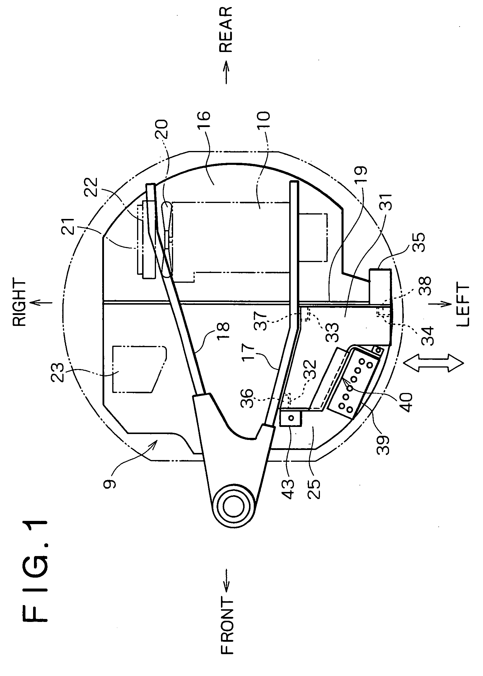
[0034]FIG. 1 shows an arrangement of devices on the upper frame 9. Numeral 16 denotes a bottom plate of the frame 9. On the bottom plate 16, main frames (may also be designated longitudinal (ribs) 17 and 18 as longitudinally extending walls are disposed on both right and left sides (as seen in a sat state of operator on the operator's seat; this is also true of the following directions of right, left and front, rear), and a transversely extending partition wall 19 is provided in a crossing relation to the frames 17 and 18. In a rear portion (engine room) of the upper frame defined by the partition wall 19, there are installed such drive units as engine 10, fan 20, radiator 21, and oil cooler 22.
[0035]On the other hand, a hydraulic oil tank 23 is installed on a front right side with respect to the partition wall 19.
[0036]As shown in FIG. 1, on a front left side in the upper frame 9, there is provided a tank / battery mounting portion 25 (hereinafter r...
second embodiment (see figs.8 to 13)
Second Embodiment (see FIGS. 8 to 13)
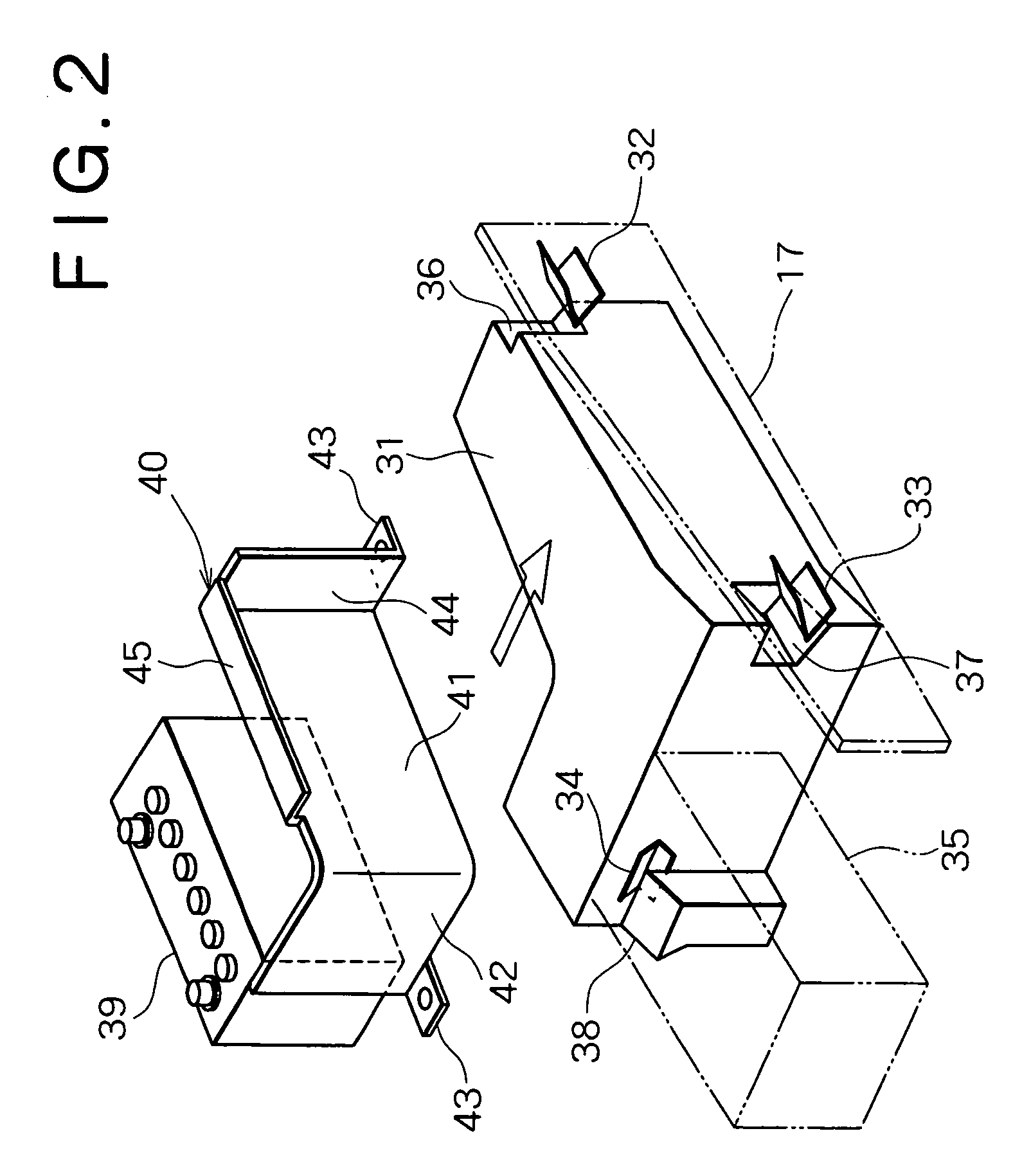
[0078]A second embodiment of the present invention will be described below with reference to FIGS. 8 to 13.
[0079]In this embodiment, the same portions as in the previous first embodiment will be identified by the same reference numerals and tautological explanations thereof will be omitted.
[0080]As illustrated in the figures, a tank 31 is formed in L shape having a rear portion bent to the left side. The tank 31 is mounted in a tank mounting portion 25 in a state in which a longitudinal side portion of the L shape is in contact with a left main frame 17 and a lower side portion thereof is in contact with a partition wall 19 (the “contact” means a closely contacted state or a closely opposed state through a slight gap).
[0081]A projecting portion 31a projecting to the frame 17 side (right side) is formed in an upper end portion of the tank 31.
[0082]The projecting portion 31a is formed in a hollow shape so as to permit the storage of fuel as part of...
PUM
 Abstract
Description
Claims
Application Information