
Transcranial magnet stimulation of deep brain targets

a transcranial magnet and target technology, applied in magnetotherapy, medical science, surgery, etc., can solve the problems of power applied to any given electromagnet, and/or the rate at which power is applied, and achieve the effect of stimulating a deep targ

Active Publication Date: 2009-06-18
BRAINSWAY
View PDF99 Cites 65 Cited by
  • Summary
  • Abstract
  • Description
  • Claims
  • Application Information

AI Technical Summary

Benefits of technology

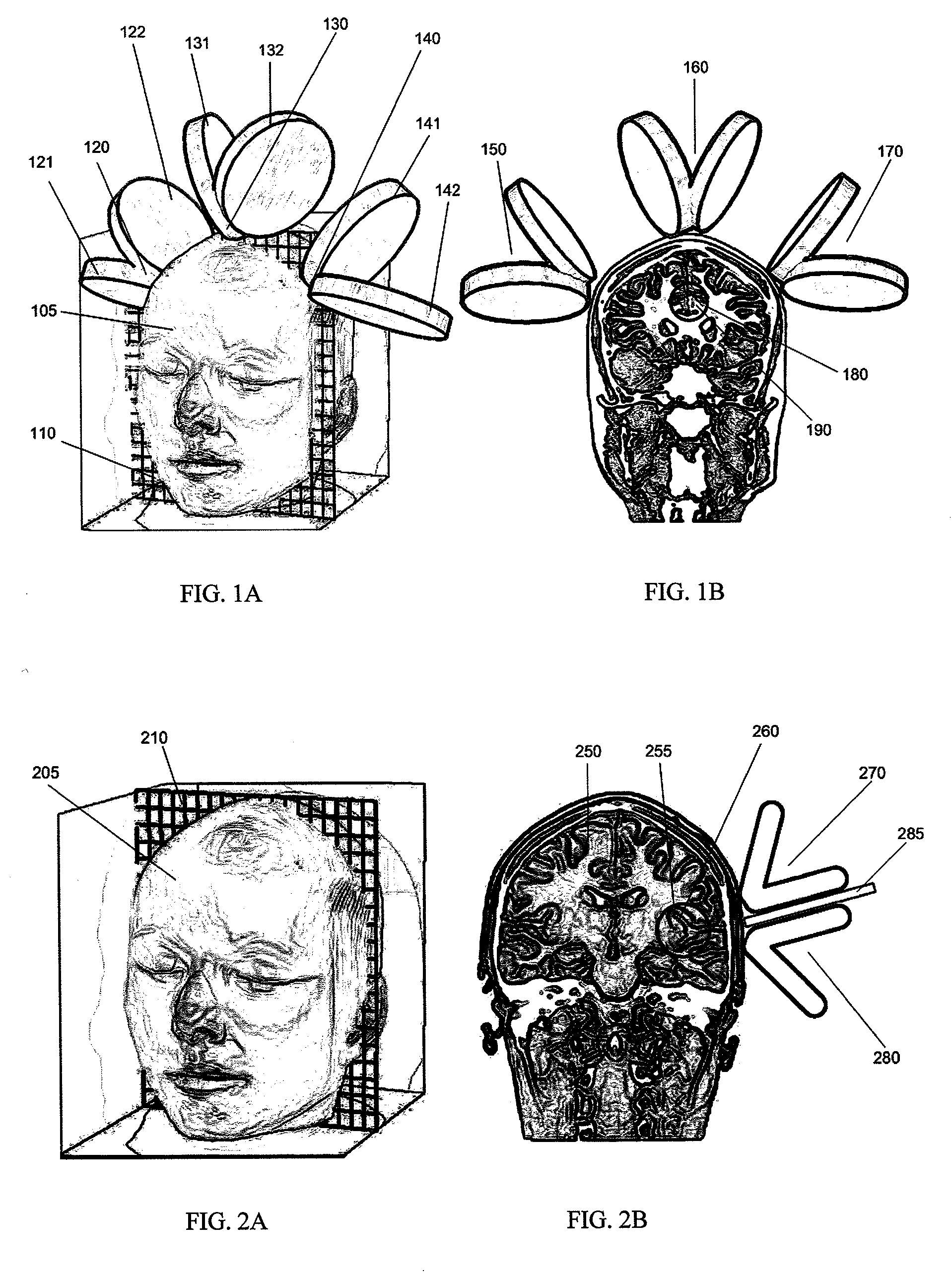
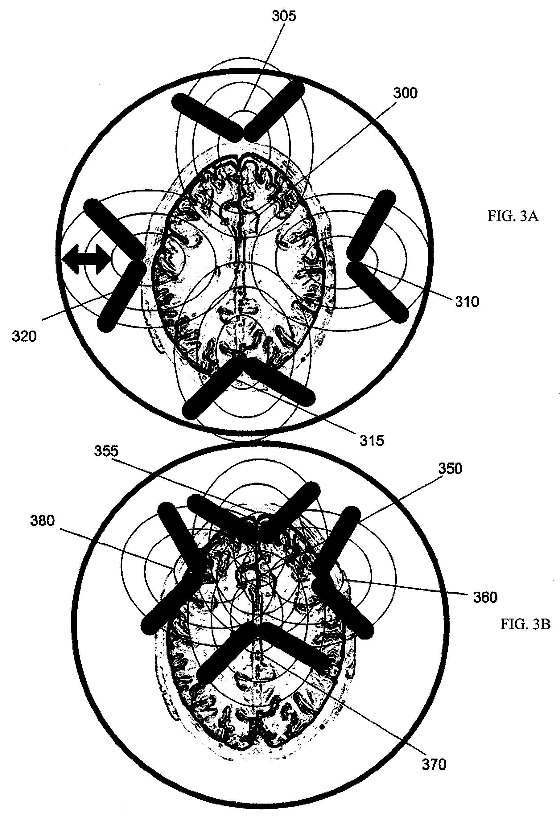
[0012]Also described herein are methods of stimulating a patient's cingulate gyrus specifically, and methods of stimulating a patient's insula specifically. For example, the methods and systems described herein may include the use of multiple magnetic coils, each pulsed serially in rapid succession, or simultaneously, followed by a longer interval before the pattern is repeated. This approach may allow impact on the activity of specific brain regions such as the dorsal anterior cingulate gyrus and associated fiber bundles and the insula. Modulating the activity of these brain regions enables the treatment of specific illnesses.
[0014]The step of positioning may include aiming the TMS electromagnet at the sulcus, wherein the sulcus is adjacent to the target deep brain region. For example, the TMS electromagnet may stimulate the sulcus to cause the electrically conductive fluid within the sulcus to transmit a current towards the deep brain target that may help depolarize the deep brain target.
[0018]For example, the step of determining the direction of the pathway through the sulcus may include determining an angle between the pathway through the sulcus and the target deep brain region. The method may also include aligning the TMS electromagnet based on the direction of the pathway through the sulcus and the angle between the pathway through the sulcus and the target deep brain region. Aligning the TMS electromagnet based on the orientation of the sulcus may help propagate the current through the sulcus to the desired deep brain target. Orienting the TMS electromagnet relative to the deep brain target may also help orient the current applied to the deep brain target.

Problems solved by technology

Thus, power applied to any given electromagnet, and / or the rate that the power is applied, is preferably limited.
While limiting the power and frequency from a single stimulating location may protect structures superficial to the deeper target, it may be impossible to effectively stimulate a deep target because of the rapid fall off of the magnetic field.

Method used


Image

  • Transcranial magnet stimulation of deep brain targets
  • Transcranial magnet stimulation of deep brain targets
  • Transcranial magnet stimulation of deep brain targets

Examples


Embodiment Construction

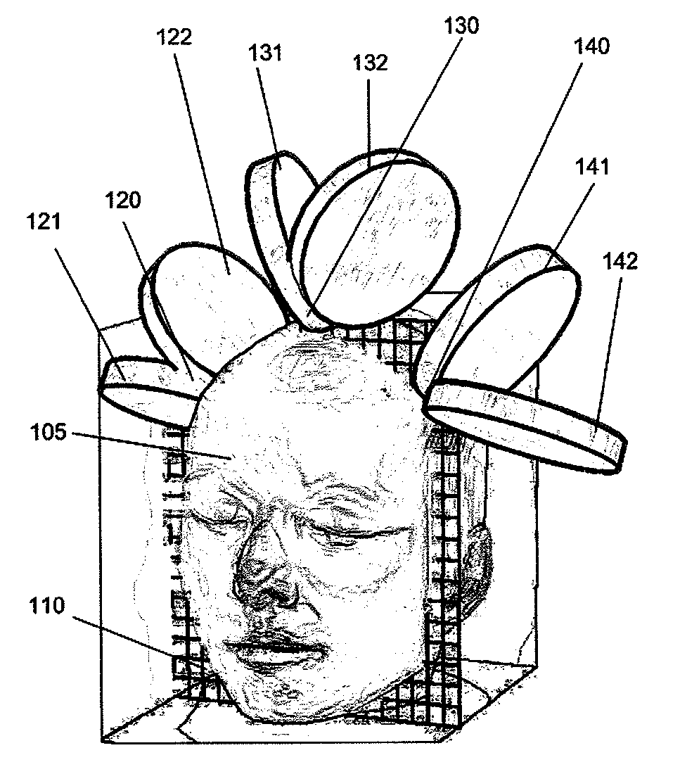
[0039]In general, the methods of Transcranial Magnetic Stimulation (TMS) described herein may be used to stimulate a deep brain region. In particular, these methods may be applied to specifically stimulate a deep brain region such as the cingulate gyrus or the insula. The method for stimulating these deep brain regions may include the steps of initially positioning one, or more typically a plurality of, TMS electromagnets around the patient's head. The plurality of TMS electromagnets may be directed at the desired deep brain target (e.g., insula or cingulate region). Alternatively, as described in greater detail below, the TMS electromagnets may be directed to a sulcus that is adjacent to the deep brain target. For example, the sulcus may be electrically continuous or connected to the deep target. Thus, any of the methods described herein may be performed in conjunction with brain imaging showing the location of the target region, as well as the configuration of any nearby sulci.

[00...


PUM


Abstract

The treatment of specific neurological and psychiatric illnesses using Transcranial Magnetic Stimulation (TMS) requires that specific neuroanatomical structures are targeted using specific pulse parameters. Described herein are methods of positioning and powering TMS electromagnets to selectively stimulate a deep brain target region while minimizing the impact on non-target regions between the TMS electromagnet and the target. Use of these configurations may involve a combination of physical, spatial and / or temporal summation. Specific approaches to achieving temporal summation are detailed.

Description

CROSS REFERENCE TO RELATED APPLICATIONS[0001]This application claims priority to the following applications: U.S. Provisional Patent Application Ser. No. 60 / 990,300, filed on Nov. 27, 2007, titled “TARGET-SPECIFIC COIL CONFIGURATIONS FOR TRANSCRANIAL MAGNETIC STIMULATION” and U.S. Provisional Patent Application Ser. No. 60 / 992,385, filed on Dec. 5, 2007, titled “CINGULATE TMS COIL CONFIGURATIONS WITH TEMPORAL SUMMATION.” These applications are herein incorporated by reference in its entirety.INCORPORATION BY REFERENCE[0002]All publications and patent applications mentioned in this specification are herein incorporated by reference in their entirety to the same extent as if each individual publication or patent application was specifically and individually indicated to be incorporated by reference.FIELD OF THE INVENTION[0003]The devices and methods described herein relate generally to the field of Transcranial Magnetic Stimulation.BACKGROUND OF THE INVENTION[0004]Transcranial Magneti...

Claims


Application Information

Patent Timeline
Patent Type & Authority Applications(United States)
IPC IPC(8): A61N2/04A61N2/02
CPCA61N2/02A61N2/006
Inventor SCHNEIDER, M. BRETMISHELEVICH, DAVID J.
Owner BRAINSWAY
Learn More