Anchoring device for securing intracranial catheter or lead wire to a patient's skull

a technology of an anchoring device and a patient's skull, which is applied in the direction of catheters, infusion needles, therapy, etc., can solve the problems of catheter tip displacement, periosteum not providing as much stability, and prone to kinking and abrasion damage, so as to achieve the effect of convenient and effective securing a catheter

Active Publication Date: 2009-06-18
CODMAN & SHURTLEFF INC
View PDF1 Cites 19 Cited by
  • Summary
  • Abstract
  • Description
  • Claims
  • Application Information

AI Technical Summary

Benefits of technology

[0015]An object of the invention is to provide a system and method for easily and effectively securing a catheter or electrical lead from a burr hole of a patient in such a manner that ensures that the catheter or lead is anchored with respect to a target site within the patient's brain and so that tension applied to the catheter or lead will not cause damage to the same.
[0016]Another object of the invention is to provide such an anchor that safely and atruamatically redirects the exterior portion of an implanted catheter or lead wire from a perpendicular trajectory (exiting from the burr hole) to a tangential path immediately adjacent the patient's scalp.

Problems solved by technology

Typically, these implantable catheters are vary delicate being only about 1 mm to 1.5 mm in outer diameter and are therefore prone to kinking and abrasive damage during handling and especially during use over their lifetime.
The periosteum does not provide as much stability as desired, and movement of the catheter anchor may result in displacement of the catheter tip.
Obviously, a patient with such intracranial leads and / or catheters in place, whether in a hospital recovery ward, or leading an active life will invariably challenge the integrity and strength of the anchoring system.
Typically, during normal patient activities, the communicating leads located outside the patient's skull will become entangled and snagged on various things and will become tugged or even violently jerked.
However, in this arrangement the lead may easily be moved, particularly axially, when the plug is forced into engagement with the socket.
This system cannot be used with catheters and any tension applied to the remote portions of the leads will act to directly remove the plug and also the socket, which will then release the lead and easily risk displacement of its distal end.
This system fails to offer any strain-relief structure that allows remote applied tension to the leads to be absorbed without dislodging the implanted distal ends from the target site.
Although the anchoring system of U.S. Pat. No. 5,464,446 is versatile by allowing both a lead wire and a catheter to exit a patient's skull atraumatically, the device is too difficult to assemble, will not hold up to even moderate applied tension, and forces a catheter to exit normal to the patient's skull thereby causing difficultly in allowing the patient to perform normal activities or even hide their medical disposition—for example, the patient cannot wear a hat without potentially kinking or damaging the catheter.
Also, the device of this prior art patent fails to offer a strain-relief function that can mitigate the displacement of the distal end of the implanted lead or catheter due to remote applied tension.

Method used


Image

  • Anchoring device for securing intracranial catheter or lead wire to a patient's skull
  • Anchoring device for securing intracranial catheter or lead wire to a patient's skull
  • Anchoring device for securing intracranial catheter or lead wire to a patient's skull

Examples


first embodiment

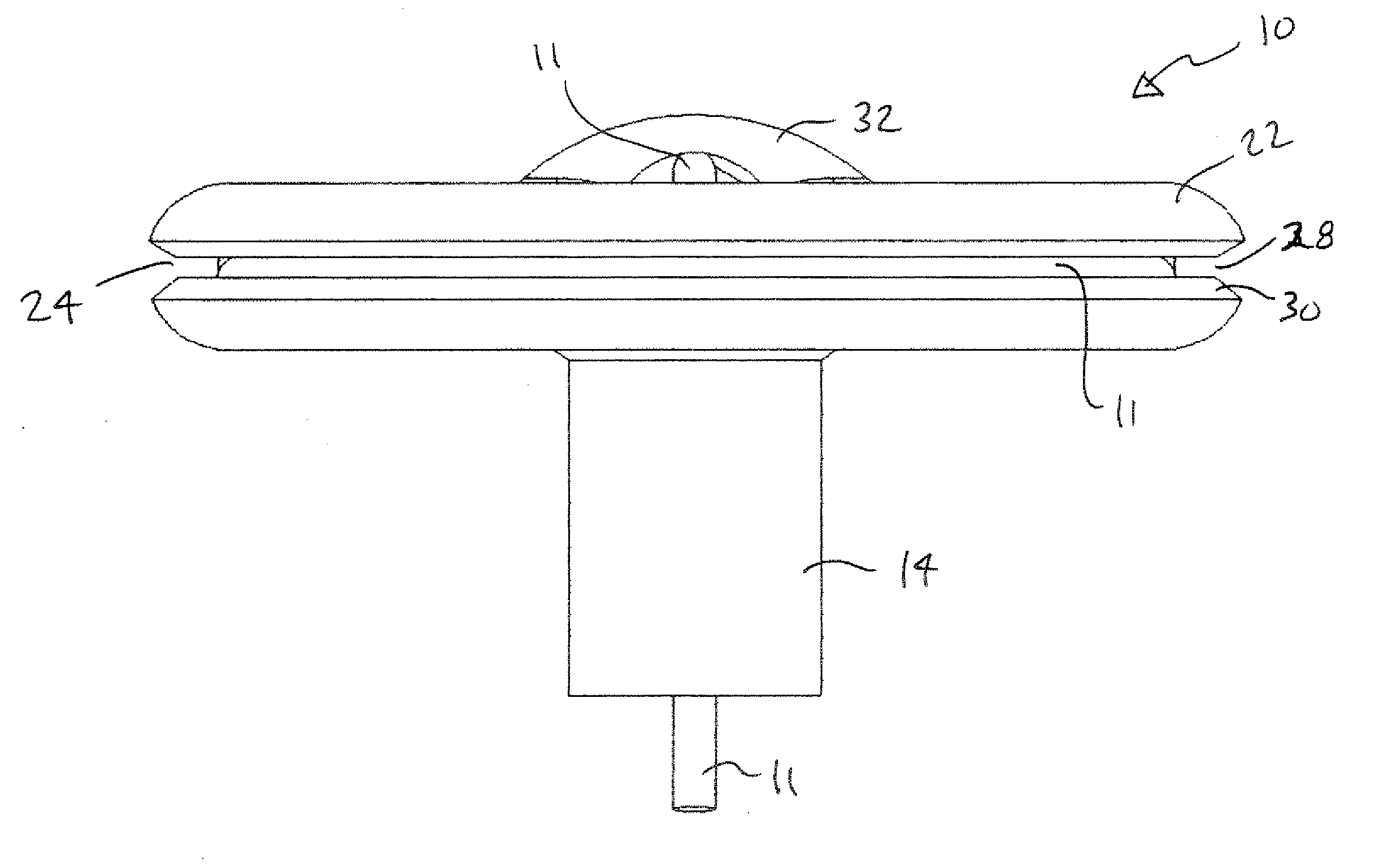
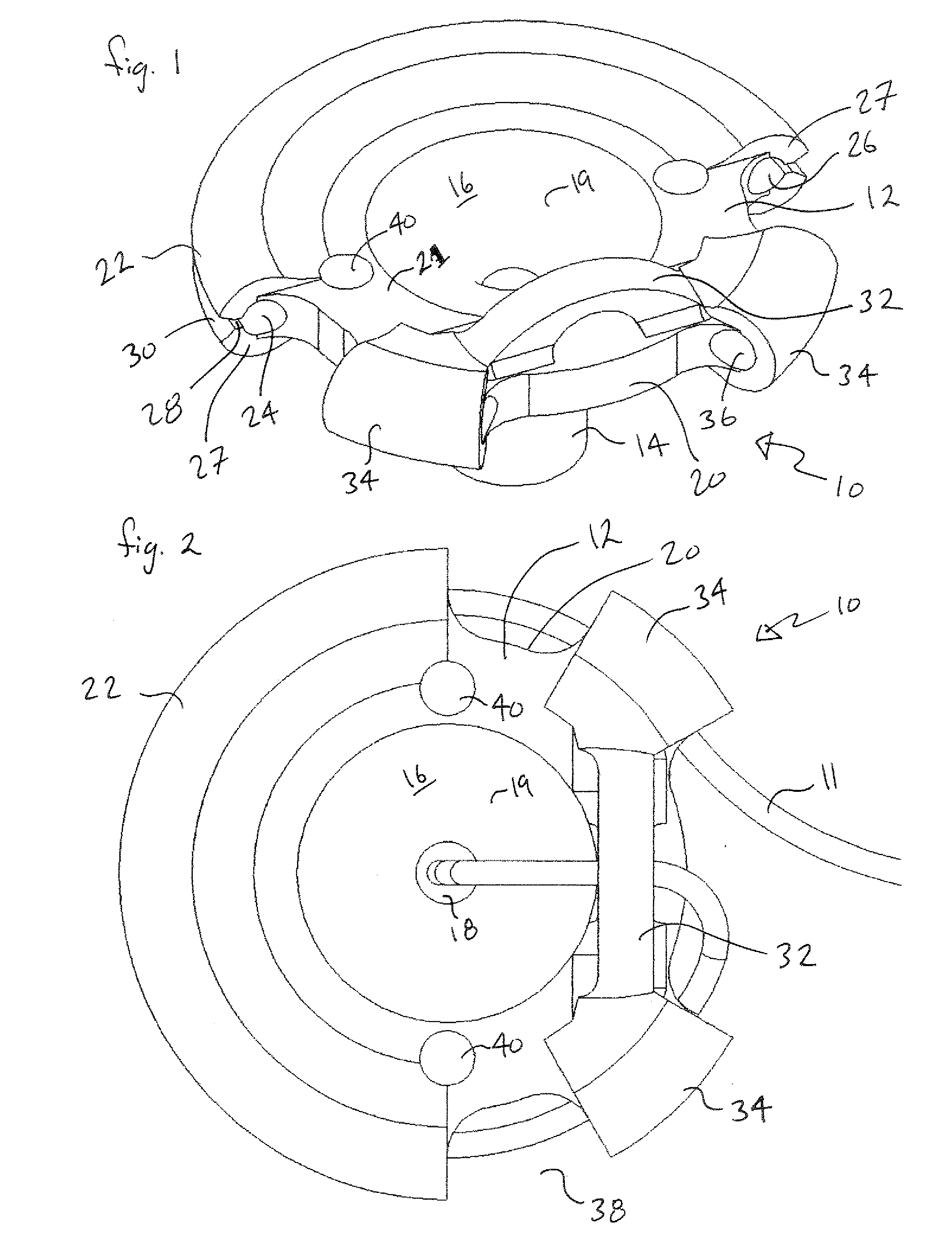
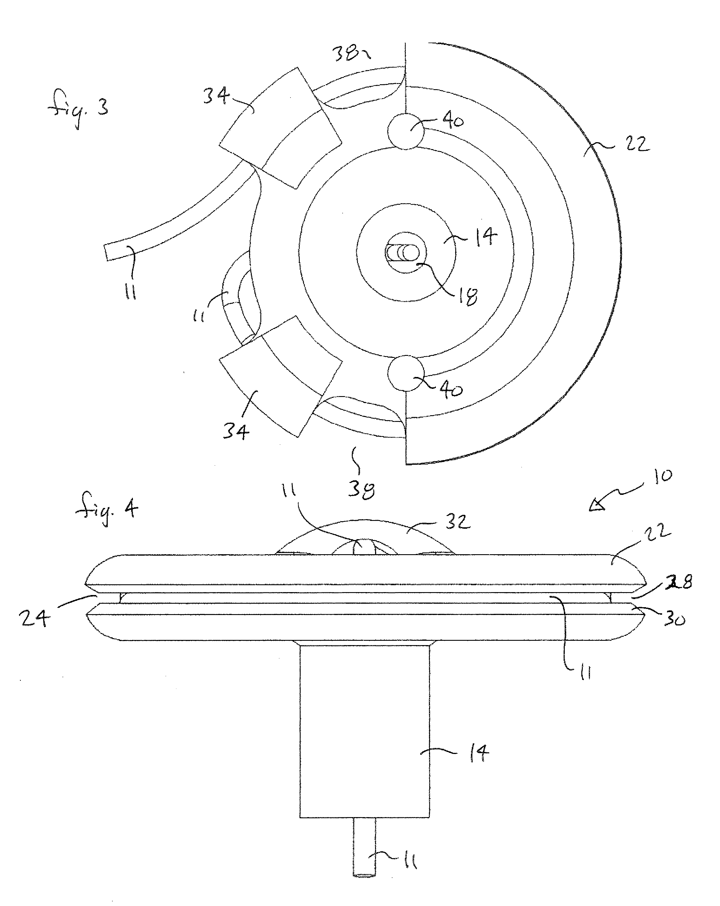
[0034]Referring now to FIGS. 1 through 9, a lead anchor 10 for securing communicating lead wires and catheter conduits (herein after collectively referred to as “lead 11”) from intracranially implanted devices is shown, according to the invention. In its basic form, as is apparent in the figures, anchor 10 is similar in shape to that of a small rubber funnel and includes a generally circular rim plate 12 and an integrally formed hollow lower stem 14. As can be seen in FIGS. 4, 5, 6, 7, and 9, lower stem 14 includes a generally cylindrical outside shape and an internal flared passage 16. Flared passage 16 connects a small lower opening 18 located at the bottom of lower stem 14 to rim plate 12 so that the flared passage 16 looks similar to the cusp shape of a trumpet horn, opening to a larger diameter at the top adjacent the rim plate 12 and defining a cusp-shaped inside surface 19. Rim plate 12 defines an upper surface 21 and a lower surface 23.

[0035]Although it is preferred that rim...

second embodiment

[0057]The number, size and exact shape of loops 150 can vary to meet the exact requirements of the particular anchoring application. Of course, the angle of each loop 11 in this second embodiment shown in FIGS. 10-13 may also vary depending on the design particulars, as can the exact durometer of the material used to make either anchor.

[0058]As can be seen in FIGS. 10, 11, and 13, rim plate 102 includes cutouts 154 along the periphery 120. The purpose of cutouts 154 is to offer a less sharp path for lead 11 to make the transition from vertically exiting flared passage 106 from the patient's brain to the more horizontal orientation about the rim plate 102 and through the loops 150. The lead 11 passes gently into any of the cutouts about the periphery 120 before entering any of the loops 150.

[0059]As shown in FIG. 13, the anchor 100 of this second embodiment further includes a sealing ring 156 located on the lower surface 123 of rim plate 102. This sealing ring 156 is meant to be inte...


PUM


Abstract

An anchor system for securing a lead to a patient's skull is disclosed. The lead is of the type that passes through a burr hole created in the patient's skull and includes a distal end which is implanted within the patient's brain at a target site. The anchor, according to a first embodiment of the invention includes a stem, an integrally formed rim plate, and a peripheral clamping structure. The clamping structure is adapted to receive and snugly hold a portion of the lead. The stem is sized and shaped to fit within the burr hole, leaving the rim plate positioned flush with the patient's skull. A flared passage is provided within the stem and rim plate so that the lead may pass through the stem and into the rim plate, at which point the lead follows the contours of the flared passage and communicates with the peripheral clamping structural. The clamping structure holds a portion of the lead so that any tension of the lead will not be transmitted past the anchor and the distal end of the lead will not become displaced from the target site. According to a second embodiment, the peripheral clamping structure includes several flexible loops that are sized and spaced from each other to allow a lead to be laced through the loops as the lead extends about the periphery of the rim plate.

Description

BACKGROUND OF THE INVENTION[0001]1. Field of the Invention[0002]The present invention generally relates to anchoring systems for securing an implanted tubular medical device to a patient, and more particularly, to such anchoring systems for securing intracranial tubular medical devices to the patient's skull.[0003]2. Description of the Prior Art[0004]Surgical procedures of a patient's brain often require implanting a medical device to a prescribed intracranial target site. The implanted medical device typically requires long-term communication between the target site and a remote site located outside the patient's skull. The device can be electrically-based wherein power or signal lead wires must link the device at the target site to the outside world, or the device may be a catheter implanted to administer a drug from a remote location precisely at the target site within the brain or perhaps positioned to shunt fluid from the target site, or a catheter that includes mapping or stim...

Claims


Application Information

Patent Timeline
Patent Type & Authority Applications(United States)
IPC IPC(8): A61N1/02
CPCA61M25/02A61M25/04A61M2025/0213A61N1/0539A61M2025/024A61M2025/0246A61M2025/028A61M2025/0233
Inventor SCHORN, GREG M.SULLIVAN, SCOTT
Owner CODMAN & SHURTLEFF INC
Why Eureka
Try Eureka