Control Method of Exhaust Gas Purification System and Exhaust Gas Purification System

a technology of exhaust gas purification system and control method, which is applied in the direction of electrical control, machine/engine, exhaust treatment electric control, etc., can solve the problems of reducing catalyst temperature, oxidation of pm, and difficulty in self-regeneration of filters, so as to reduce the number of meshes of the data map of the data for the fuel pressure control in the forced regeneration control and the like , the effect of preventing torque shock

Active Publication Date: 2009-07-02
ISUZU MOTORS LTD
View PDF17 Cites 10 Cited by
  • Summary
  • Abstract
  • Description
  • Claims
  • Application Information

AI Technical Summary

Benefits of technology

[0028]According to the control method of exhaust gas purification system and the exhaust gas purification system according to the present invention, since in the forced regeneration control of the exhaust gas purification device such as a continuous regeneration type DPF device, an NOx purification device and the like, data for control of normal operation control can be used in a portion for the normal injection control region corresponding to the high-load operation state, data for control for the forced regeneration control is reduced.
[0029]Also, in the forced regeneration control, even at transition between the multi-injection ...

Problems solved by technology

However, if the exhaust gas temperature is low, the temperature of a catalyst is lowered and not activated.
Thus, the oxidation reaction is not promoted, and oxidation of the PM and self-regeneration of the filter become difficult.
As a result, accumulation of PM on the filter continues and clogging of the filter progresses, which results in a problem of exhaust pressure rise due to the clogging of the filter.
However, since the forced regeneration control might be executed during travelling or stopp...

Method used


Image

  • Control Method of Exhaust Gas Purification System and Exhaust Gas Purification System
  • Control Method of Exhaust Gas Purification System and Exhaust Gas Purification System
  • Control Method of Exhaust Gas Purification System and Exhaust Gas Purification System

Examples


Embodiment Construction

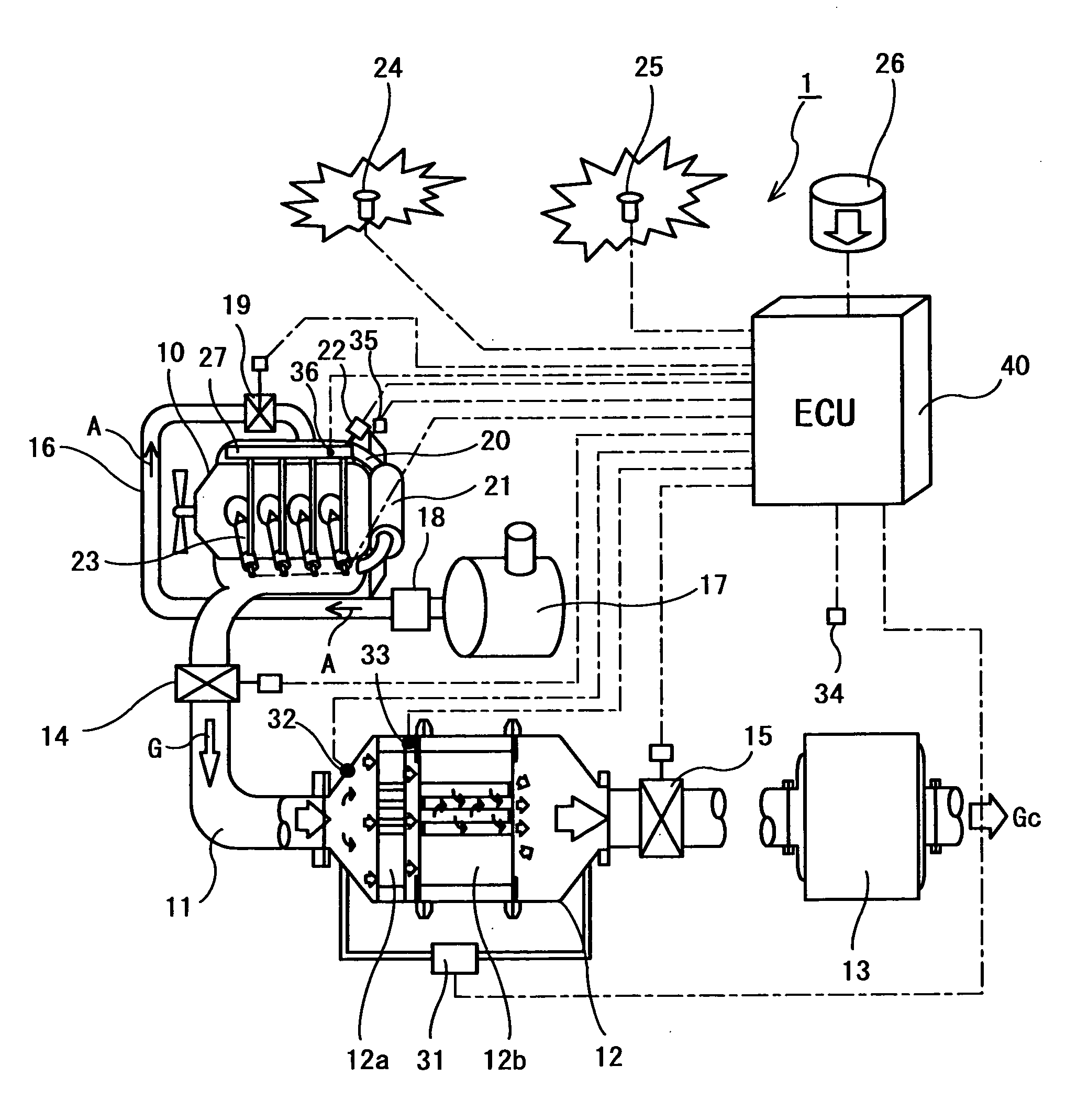
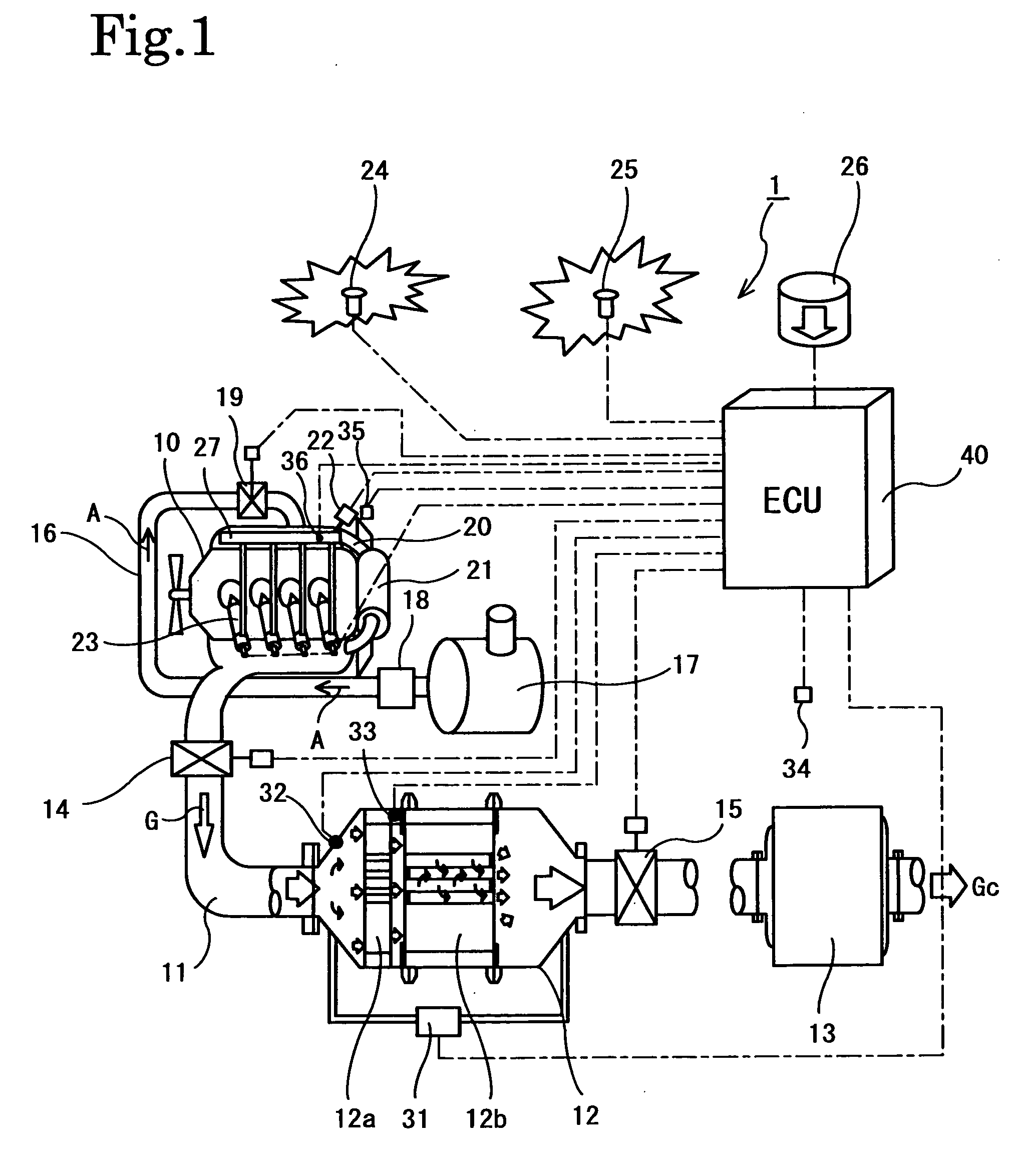
[0058]The control method of exhaust gas purification system and an exhaust gas purification system of an embodiment according to the present invention will be described below referring to the attached drawings using a continuous regeneration type DPF (Diesel Particulate Filter) device as an example. FIG. 1 shows configuration of an exhaust gas purification system 1 of this embodiment.

[0059]The exhaust gas purification system 1 comprises an exhaust gas purification device 12 in an exhaust passage 11 of a diesel engine (internal combustion engine) 10. This exhaust gas purification device 12 is one of continuous regeneration type DPF devices. The exhaust gas purification device 12 comprises an oxidation catalyst device 12a on the upstream side and a filter device 12b with catalyst on the downstream side. Moreover, on the downstream side of the exhaust gas purification device 12, a silencer 13 is provided. Also, on the upstream side of the exhaust gas purification device 12, an exhaust ...


PUM


Abstract

In forced regeneration control of an exhaust gas purification device 12, data for control such as the number of meshes of a data map and the number of data maps for forced regeneration control is reduced and occurrence of torque shock is avoided by smoothly changing a fuel pressure. In the forced regeneration control of the exhaust gas purification device 12, when an operation state of an internal combustion engine 10 is a high-load operation state, normal injection control by stopping multi injection is carried out and according to a rotation speed Ne and a load Q of the internal combustion engine 10, a region for control is divided into a multi-injection control region Rm, a transition region Rt, and a normal injection control region Rn, and in the transition region Rt, data Pt for fuel pressure control obtained by interpolation of data Pml for fuel pressure control on the multi-injection control region Rm side and data Pnl for fuel pressure control on the normal injection control region Rn side is used.

Description

BACKGROUND OF THE INVENTION[0001]The present invention relates to a control method of exhaust gas purification system and an exhaust gas purification system that can simplify data for fuel pressure control and prevent occurrence of a torque shock at forced regeneration control accompanying multi injection of an exhaust gas purification device such as a continuous regeneration type DPF device or an NOx purification device.DESCRIPTION OF THE RELATED ART[0002]Regulations on emissions of the particulate matter (PM: particulate matter: Hereinafter referred to as PM) as well as NOx, CO, HC and the like exhausted from a diesel engine have been tightened year by year. A technology has been developed that the PM is trapped by a filter called a diesel particulate filter (DPF: Diesel Particulate Filter: Hereinafter referred to as DPF) so as to reduce the PM amount exhausted to the outside. A continuous regeneration type DPF device carrying a catalyst is among them.[0003]This continuous regener...

Claims


Application Information

Patent Timeline
IPC IPC(8): F01N9/00
CPCF01N3/02F01N3/20F02D41/027F02D41/2416Y02T10/20F02D2250/21F02D2250/31Y02T10/44F02D41/402Y02T10/12Y02T10/40
Inventor HASEYAMA, TAKASHIGOTOU, SHINJIHAGIO, KENJIMASHIKO, TATSUOWATANABE, YOSHINOBU
Owner ISUZU MOTORS LTD
Why Eureka
Try Eureka