Heat sink

a heat sink and heat sink technology, applied in lighting and heating apparatus, semiconductor devices, semiconductor/solid-state device details, etc., can solve the problems of heat dissipation problem in the dual-in-line package electronic components, the contact between the heat sink and the electronic components is not perfect, and the ics will have even higher heat emission

Inactive Publication Date: 2009-07-02
HONG FU JIN PRECISION IND (SHENZHEN) CO LTD +1
View PDF20 Cites 8 Cited by
  • Summary
  • Abstract
  • Description
  • Claims
  • Application Information

AI Technical Summary

Problems solved by technology

As technology continues to advance, it is inevitable that electronic components such as integrated circuits (ICs) will incorporate even larger numbers of transistors and other such dual-in-line electronic components in their construction, and accordingly, these ICs will have even higher level of heat emission.
The conta

Method used


Image

  • Heat sink
  • Heat sink
  • Heat sink

Examples


Embodiment Construction

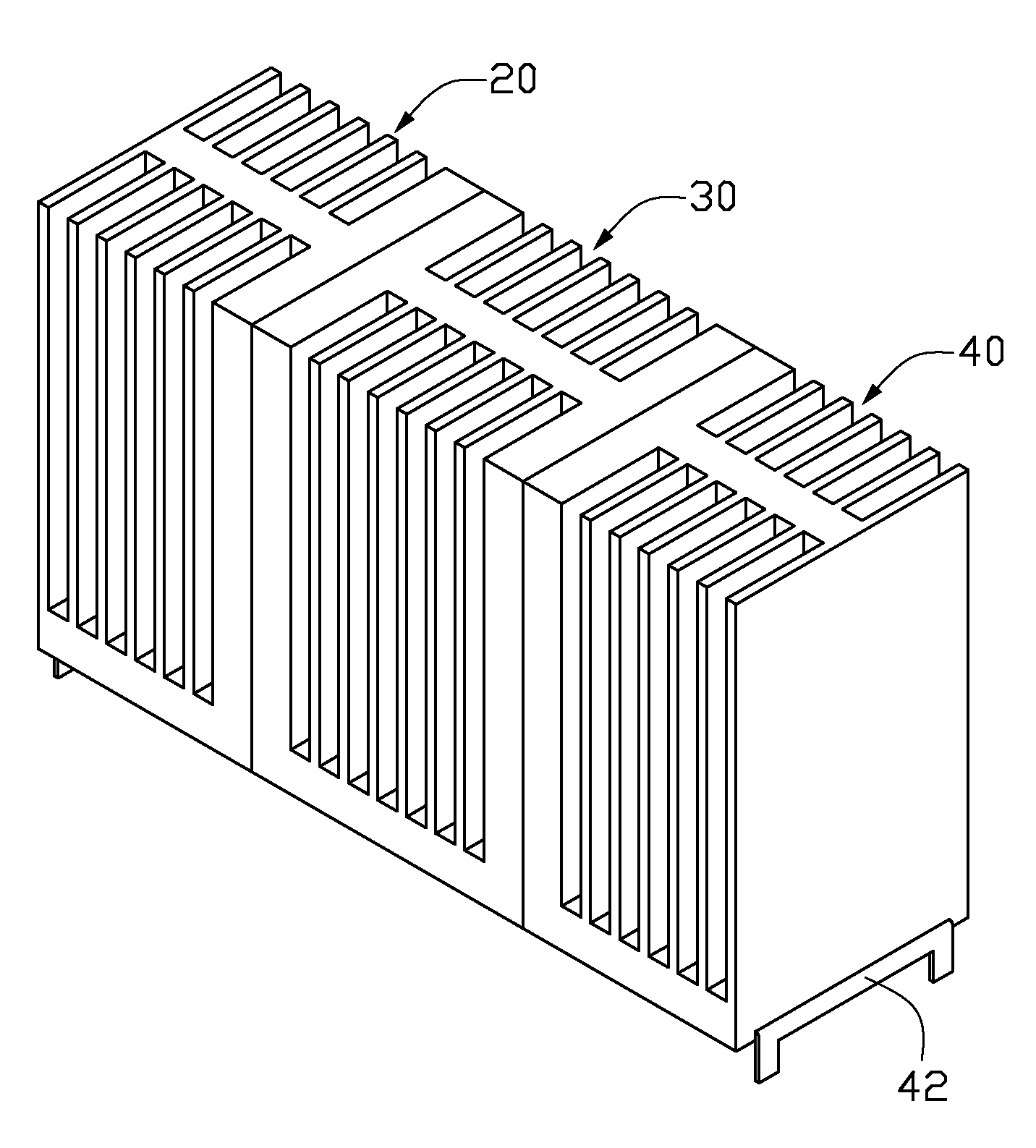
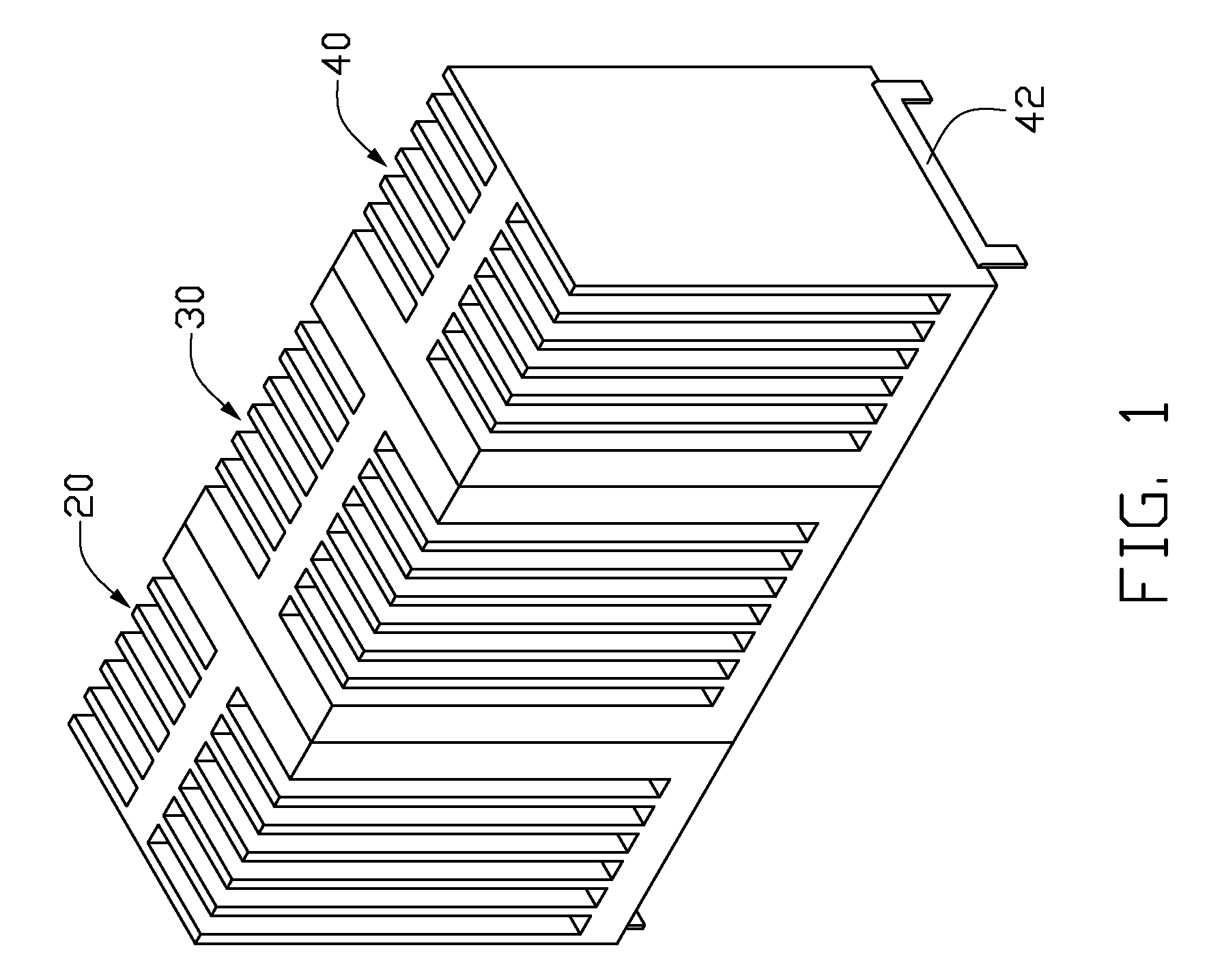
[0014]Referring to FIG. 1, the heat sink according to the first embodiment includes a first fin unit 20, a second fin unit 30 and a third fin unit 40 connected in series, wherein the second fin unit 30 is interconnected between the first fin unit 20 and the third fin unit 40.

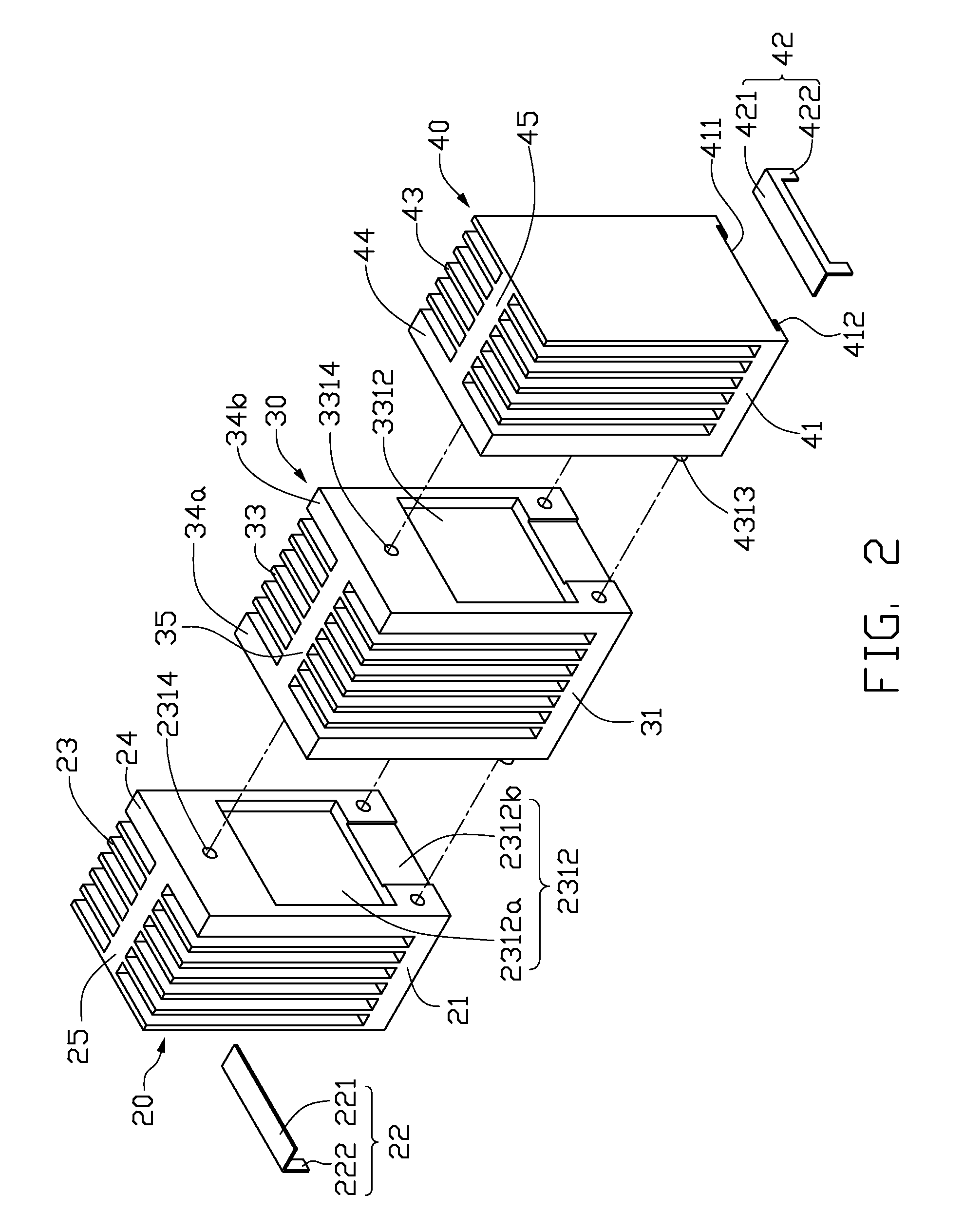
[0015]Referring to FIG. 2 and FIG. 3, the first fin unit 20 includes a base 21, a fixing frame 22, a plurality of stacked heat dissipation fins 23, a sidewall 24 and a heat dissipation wall 25. The base 21 is plate-shaped, which has a top surface and an opposite bottom surface. The heat dissipation fins 23 are extended upwardly and perpendicularly from the top surface of the base 21. The heat dissipation fins 23 are paralleled and spaced to each other, and each of the heat dissipation fins 23 is arranged along a first direction of the base 21. The heat dissipation wall 25 is extended upwardly and perpendicularly from the top surface of the base 21, and is arranged along a second direction of the base 21 that is ...


PUM


Abstract

A heat sink for dissipation heat for an electronic components (50) having a dual-in-line package comprises at least two fin units (20, 30, 40). Each of the fin units comprises a base (21, 31, 41) and a plurality of heat dissipation fins (23, 33, 43) extending upwardly from the base. At least one fixing hole (2314, 3314) is formed in one of the fin units. At least one fixing poles (3313, 4313) is formed in another neighboring fin unit. The two neighboring fin units are assembled together with the at least one fixing pole inserted in the at least one fixing hole. A receiving space is defined between the two neighboring fin units for receiving the electronic component therein.

Description

BACKGROUND OF THE INVENTION[0001]1. Field of the Invention[0002]The present invention relates generally to heat sinks, and more particularly to a heat sink for dissipation heat for dual-in-line package electronic components.[0003]2. Description of Related Art[0004]As technology continues to advance, it is inevitable that electronic components such as integrated circuits (ICs) will incorporate even larger numbers of transistors and other such dual-in-line electronic components in their construction, and accordingly, these ICs will have even higher level of heat emission.[0005]In order to reduce the high temperature resulting from operations of the electronic components, heat sinks are commonly used. Conventional heat sinks generally comprise a base and a plurality of fins extending upwardly from the base. The heat sink is attached to one side of the electronic component by a clip. The contact between the heat sink and the electronic component is not perfect, as the heat sink is only ...

Claims


Application Information

Patent Timeline
IPC IPC(8): F28F7/00
CPCH01L23/367H01L23/4006H01L2023/405H01L2023/4056H01L2924/0002H01L2023/4087H01L2924/00
Inventor MA, HONG-GANGHUANG, XUWEI, WEIWEI, ZHEN-MIN
Owner HONG FU JIN PRECISION IND (SHENZHEN) CO LTD
Why Eureka
Try Eureka