

Spool brake device of dual-bearing reel
a brake device and reel technology, applied in the direction of reels, applications, fishing, etc., can solve the problem that the mechanical spool brake device cannot arbitrarily control the braking force, and achieve the effect of prolong and optimizing the flying distance of the tackl
Active Publication Date: 2009-07-02
SHIMANO INC
View PDF8 Cites 48 Cited by
- Summary
- Abstract
- Description
- Claims
- Application Information
AI Technical Summary
Benefits of technology
The present invention provides a spool brake device for a dual-bearing reel that can automatically adjust the strength of the braking force based on the fishing condition without resetting the braking force. This allows for a more efficient and effective use of the spool brake device in different fishing environments. The spool brake device includes a spool brake portion, a first braking force setting portion, a tension detection portion, a second braking force setting portion, and a spool control portion. The spool control portion is configured to control the spool brake portion with the first braking force when the detected tension is equal to or less than a reference tension. The second braking force is generated by multiplying the first braking force and is applied when the detected tension exceeds the reference tension. The spool brake device also includes a timer portion and a velocity detection portion to further improve the control of the spool brake device.
Problems solved by technology
However, the mechanical spool brake device is not allowed to arbitrarily control the braking force during casting.
Method used
View moreImage
Smart ImageViewing Examples

Examples
example embodiment (
f)
[0109]In the above-mentioned embodiment, a plurality of reference tensions may be set depending on a plurality of first braking forces.
Login to View More PUM
 Abstract
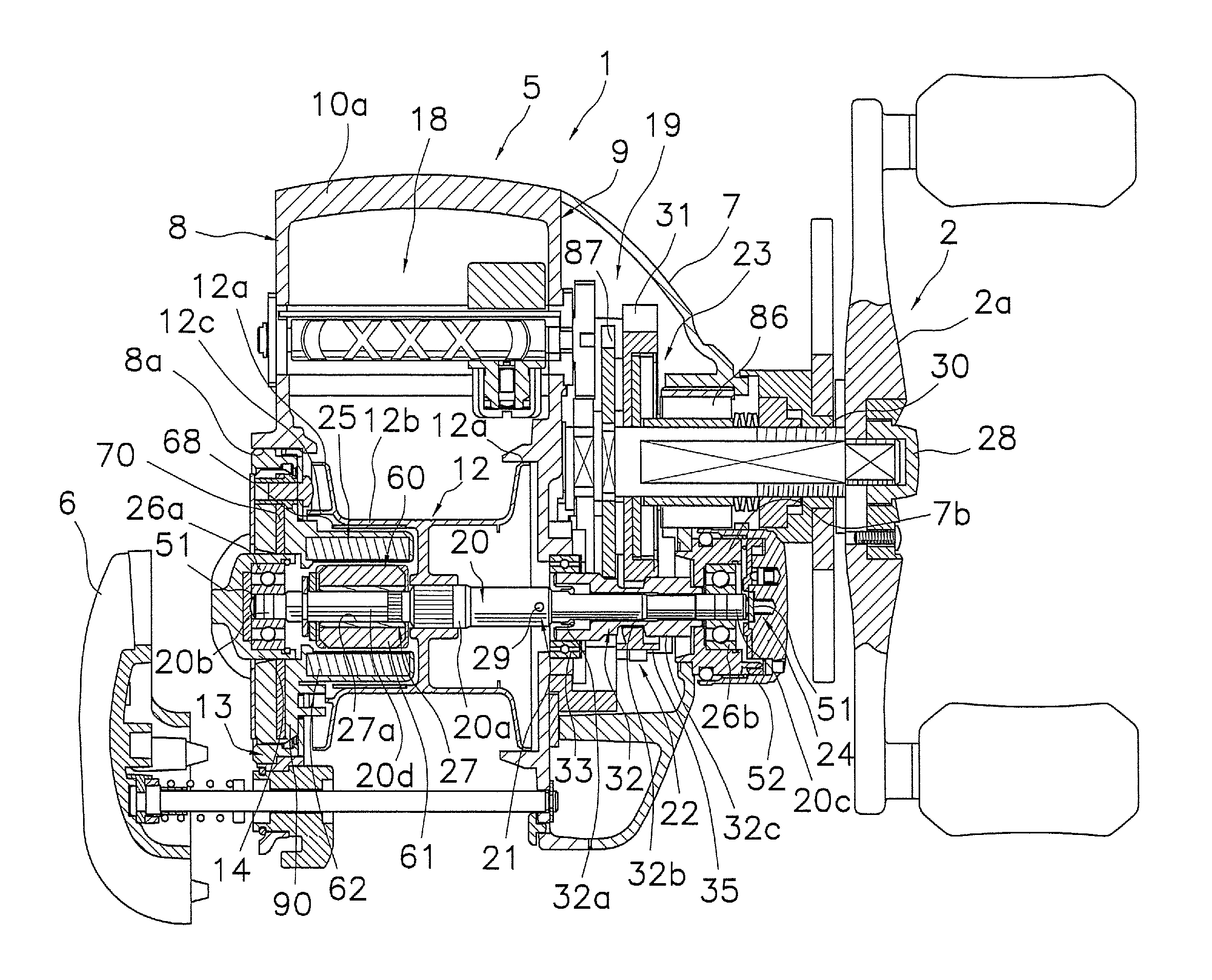
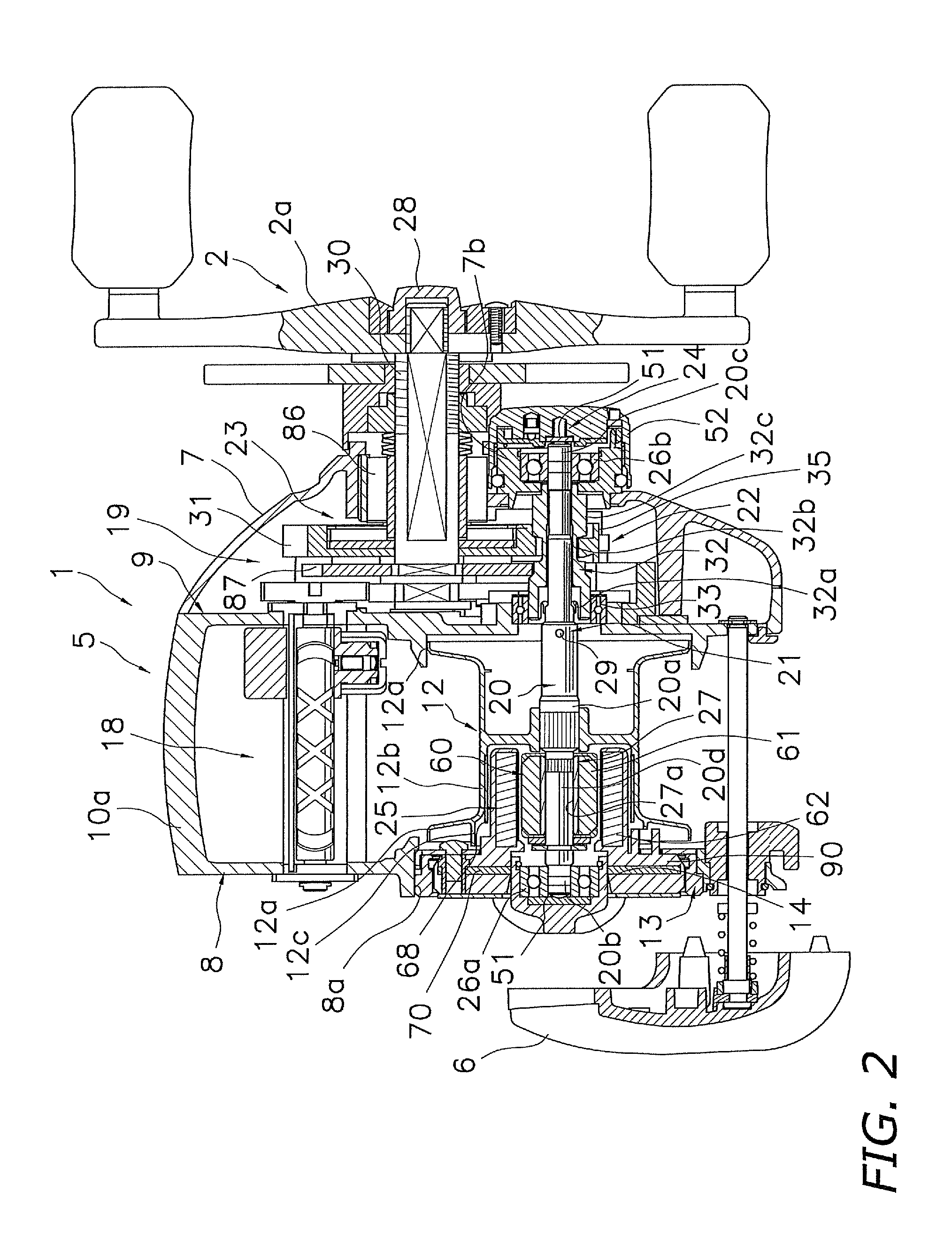
A spool brake mechanism 25 is a device for braking a spool. The spool brake mechanism 25 includes a spool brake member 40 and a control component 55. The control component 55 is configured to control a spool brake member with first braking force. The control component 55 is also configured to control the spool brake member with second braking force when tension detected by a tension detection member becomes equal to or less than a reference tension.
Description
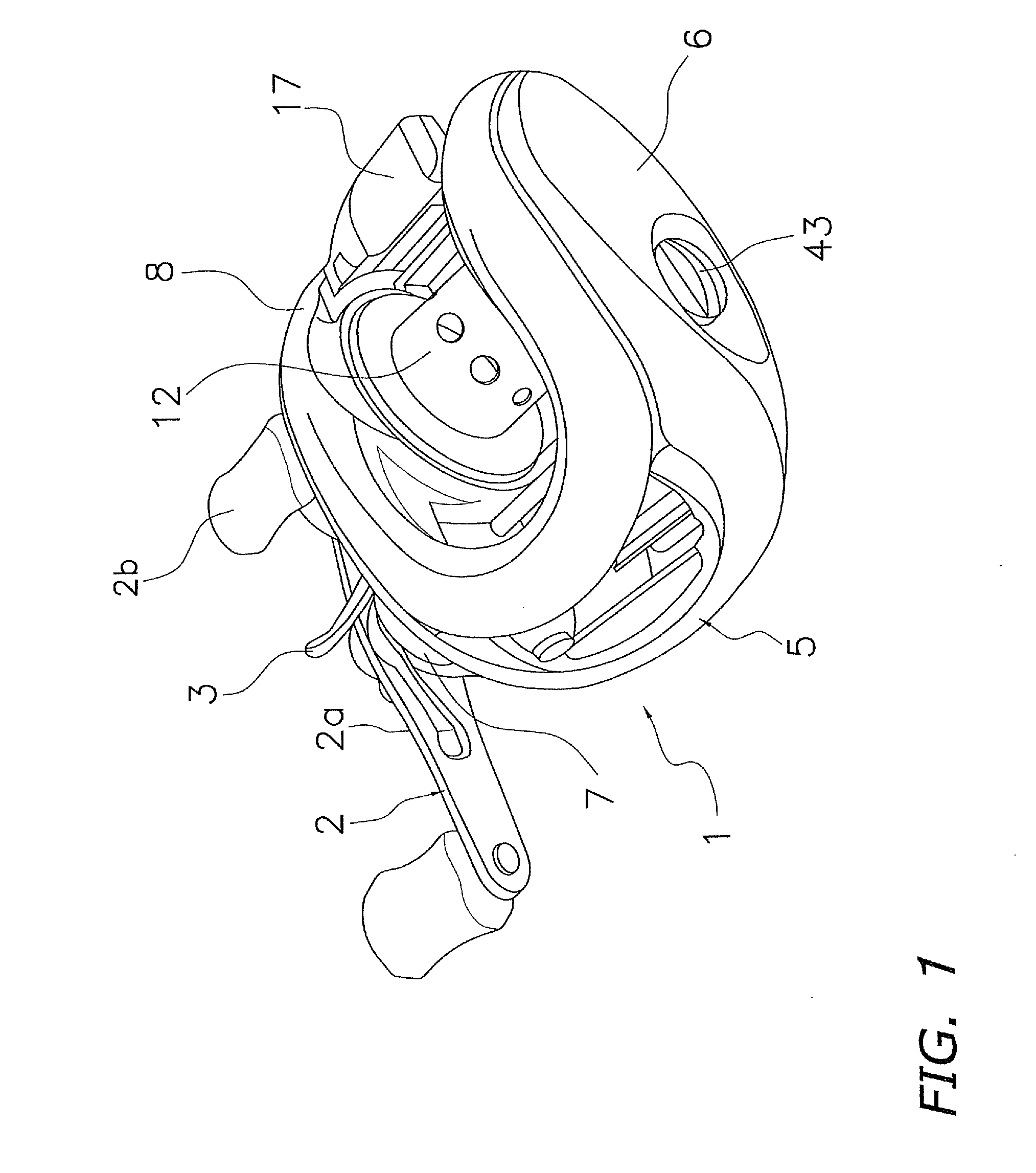
CROSS-REFERENCE TO RELATED APPLICATIONS[0001]This application claims priority under 35 U.S.C. § 119 to Japanese Patent Application No. 2007-340399 filed on Dec. 28, 2007. The entire disclosure of Japanese Patent Application No. 2007-340399 is hereby incorporated herein by reference.BACKGROUND OF THE INVENTION[0002]1. Field of the Invention[0003]Aspects of the present invention generally relates to a brake device, and more specifically, the present invention relates to a spool brake device of a dual-bearing reel for braking a spool rotatably mounted to a reel unit.[0004]2. Background Information[0005]A bait-casting reel is a sort of a dual-bearing reel for performing casting while a fishing gear (e.g., terminal tackle) is mounted to the tip of a fishing line. The dual bearing reel, especially, the bait-casting reel is provided with a spool brake device for braking spool. The spool brake device prevents backlash in casting. Conventionally, a mechanical spool brake device has been used...
Claims
Login to View More Application Information
Patent Timeline
 Patent Type & AuthorityApplications(United States)
IPC IPC(8): A01K89/033A01K89/0155
CPCA01K89/01555A01K89/033A01K89/00
InventorNIITSUMA, AKIRAKAWASAKI, KEN'ICHI
OwnerSHIMANO INC