
Vehicle Clip Method and Apparatus

a technology of vehicle parts and clips, applied in the field of clips, can solve the problems of vibration transmission vibrations being transferred between vehicles and components, resonance and transmitting vibrations, etc., and achieve the effect of reducing and/or eliminating the transmission of vibrations

Inactive Publication Date: 2009-07-02
HONDA MOTOR CO LTD
View PDF18 Cites 28 Cited by
  • Summary
  • Abstract
  • Description
  • Claims
  • Application Information

AI Technical Summary

Benefits of technology

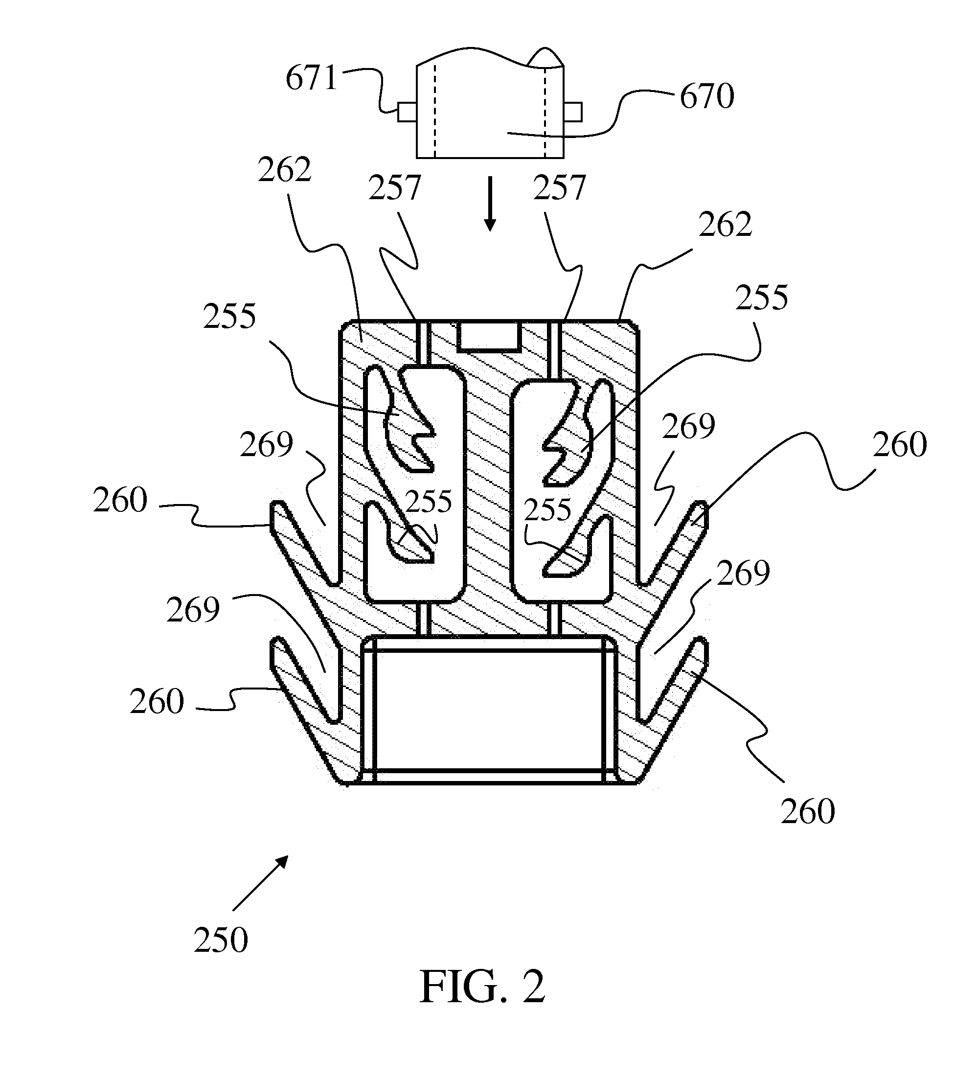
[0007]The disclosed subject matter addresses the drawbacks in the conventional vibration clip devices by providing a two piece clip structure for attachment to a vehicle. The clip structure is also capable of receiving and retaining components, such as fuel pipes, brake pipes, pneumatic or other tubes, wire harnesses, etc. The clip structure according to the disclosed embodiments reduces and / or eliminates the transfer of vibrations between the attached component(s) and the vehicle. According to one aspect of the disclosed embodiments, the clip device includes a base section and an attachment structure whereby the base structure and attachment structure are not in contact with each other.
[0008]According to another aspect of the disclosed subject matter, a flexible material is deposited between the base structure and the attachment structure which dampens vibrations from the base section and prevents them from being transferred to the attachment structure which is in contact with a vehicle body.
[0015]According to another aspect of the disclosed subject matter, a method for connecting components to a vehicle can include providing a base section having at least one receiver configured to receive at least one component, the base section having an opening including a base mating structure located in the opening, providing an attachment structure having at least one attachment mating structure, placing the attachment structure in the opening of the base section such that the attachment mating structure will contact the base mating structure to prevent movement of the base section in a first downward direction after a predetermined amount of movement of the base section relative to the attachment structure in the first downward direction, and locating a vibration damping material in the opening of the base section such that the base section is spaced from the attachment structure.

Problems solved by technology

In some cases, the pipes and cables held by such clips may resonate and transmit vibrations generated by the vehicle engine, fuel pumps, road vibration, etc.
These vibrations can be transmitted to the passenger cabin and / or other vehicle components, and in some cases can be heard and / or felt by passengers of the vehicle and / or become destructive forces that deteriorate vehicle components.
The unitary design of conventional vibration absorbing clamps often results in vibrations being transferred between the vehicle and components mounted on the clamps.
In addition, in many cases, the vibration absorbing material or damper becomes brittle due to age, sunlight, adverse environmental conditions, etc.
In this case, when the vibration absorbing material or damper becomes brittle or deteriorates, the clamp becomes less effective and may actually fail because the component that is being held either slips out or vibrates out of the clamp.

Method used


Image

  • Vehicle Clip Method and Apparatus
  • Vehicle Clip Method and Apparatus
  • Vehicle Clip Method and Apparatus

Examples


Embodiment Construction

[0023]The disclosed subject matter provides a system and method for a clip device for gripping components and attaching to a vehicle body in a manner that reduces and / or eliminates the transfer of vibrations from the vehicle to the attached components while providing a safeguard against clip attachment failure due to deterioration or damage to the vibration damper material therein.

[0024]Referring to the drawing figures, like reference numerals designate identical or corresponding elements throughout the several figures.

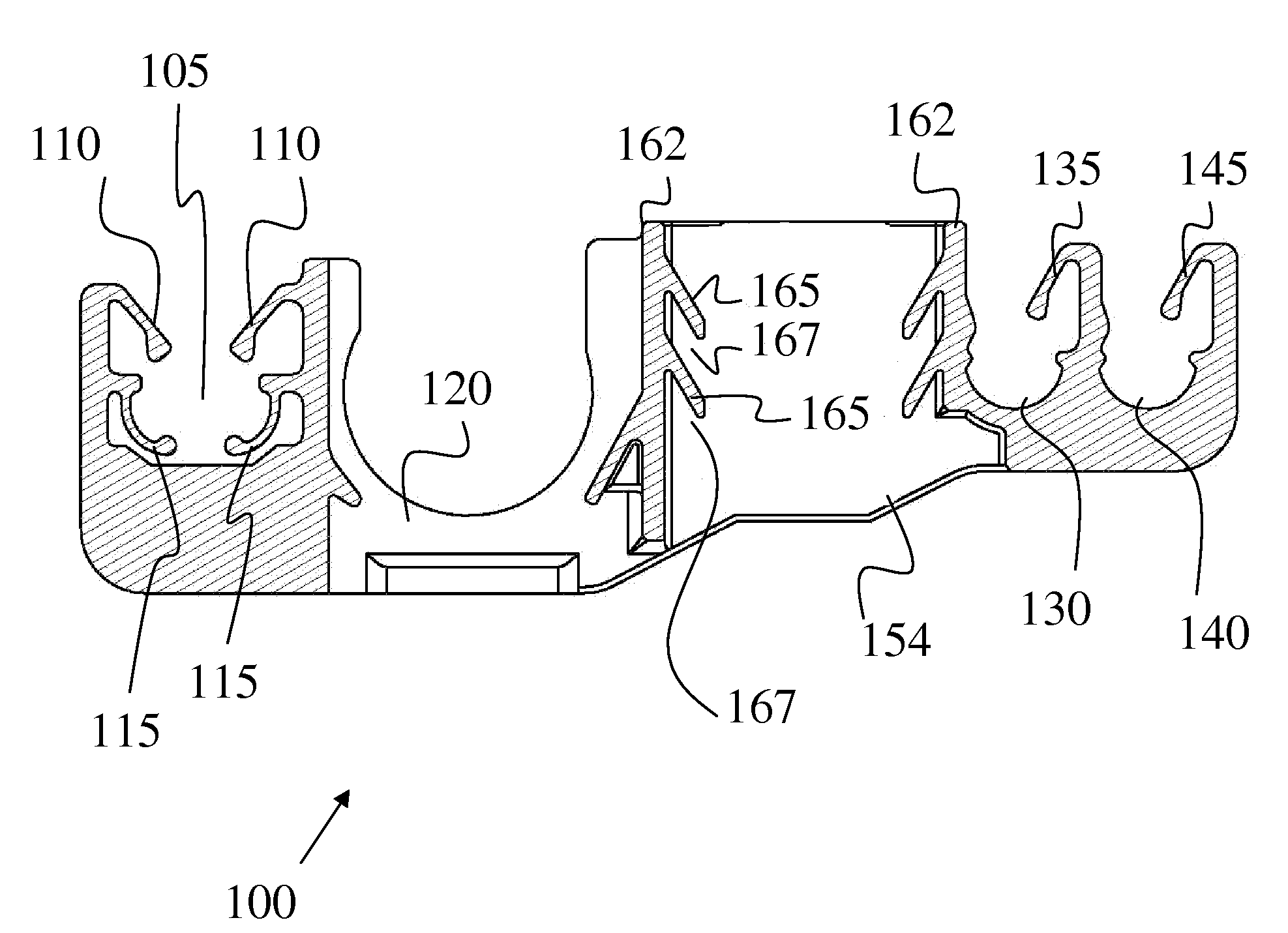
[0025]FIG. 1 illustrates a cross-sectional front view of an exemplary embodiment of a first section 100 of a clip device made in accordance with principles of the disclosed subject matter. The first section 100 can also be referred to as a base section 100 of a clip device 300 that includes a base section 100, an attachment structure 250, and a vibration damping material 310 therebetween as shown in FIG. 3. The base section 100 and attachment structure 250 may be made...


PUM


Abstract

A two piece clip device is provided which can retain various components to a vehicle while reducing and / or eliminating the transfer of vibrations from the components to the vehicle. The clip device includes a base section having receivers capable of receiving and retaining components, such as fuel pipes, brake pipes and wire harnesses. The clip device also includes an attachment structure for attaching the entire clip device to a vehicle. A flexible material is deposited between the base section and the attachment structure so that the base section and attachment structure are not in contact with each other.

Description

[0001]This application claims the priority benefit under 35 U.S.C. §119 of U.S. Provisional Patent Application No. 61 / 018,429 filed on Dec. 31, 2007, which is hereby incorporated in its entirety by reference.BACKGROUND[0002]1. Field[0003]The presently disclosed subject matter relates to a clip for gripping a component such as a pipe, tube, conduit, wire, wire harness, etc., to attach the component(s) to a support, such as a vehicle body, and more particularly, to a two piece clip device for gripping component(s) and attaching to a vehicle body. The clip can be configured to minimize the transfer of vehicle body vibrations to the attached component(s) while also safeguarding against detachment from the vehicle body should the damper material fail. The clip also isolates the pipes from transferring noise into the body.[0004]2. Brief Description of the Related Art[0005]Various clamping structures are provided in vehicles to retain components such as fuel pipes, brake pipes and wire har...

Claims


Application Information

Patent Timeline
IPC IPC(8): A47B96/06F16L3/08
CPCF16L55/035F16L3/223F16B7/0433
Inventor VOLCHKO, SCOTT JEFFREY
Owner HONDA MOTOR CO LTD
Learn More