Suspended passive element for MEMS devices

a passive element and passive element technology, applied in the field of microelectromechanical systems, can solve the problems of low noise and low power consumption of sensors and/or actuators, mems devices targeting applications requiring high-precision, and not meeting the target specification, so as to reduce or eliminate the transfer of strain

Inactive Publication Date: 2014-12-11
SILICON LAB INC
View PDF3 Cites 10 Cited by
  • Summary
  • Abstract
  • Description
  • Claims
  • Application Information

AI Technical Summary

Benefits of technology

[0012]A technique decouples a microelectromechanical system (MEMS) device from sources of strain by forming a MEMS structure with suspended electrodes that are mechanically anchored in a manner that reduces or eliminates transfer of strain from the substrate into the structure, or transfers strain to electrodes and body so that a transducer is strain-tolerant. The technique includes using an electrically insulating material embedded in a conductive structural material for mechanical coupling and electrical isolation.

Problems solved by technology

MEMS devices using capacitive transducers are easy to manufacture and result in low noise and low power consumption sensors and / or actuators.
MEMS devices targeting applications requiring high-precision (e.g., resonators having resonant frequency specifications required to be within + / −10 parts-per-million (ppm)) may not achieve the target specification due to effects of environmental factors on the resonant frequency.
However, the power, accuracy, and stability specifications may be difficult to achieve using the conventional MEMS device of FIG. 1.

Method used


Image

  • Suspended passive element for MEMS devices
  • Suspended passive element for MEMS devices
  • Suspended passive element for MEMS devices

Examples


Embodiment Construction

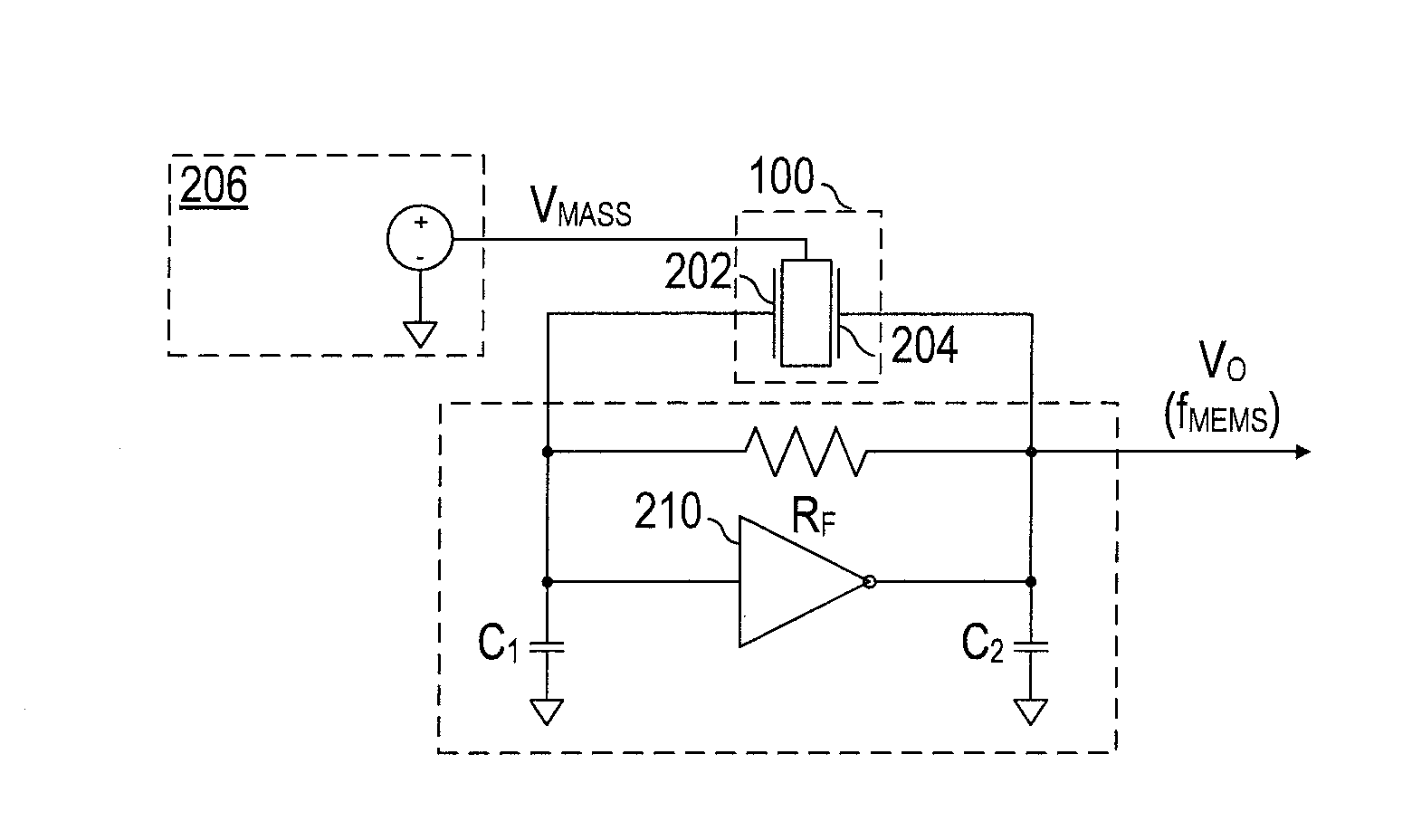
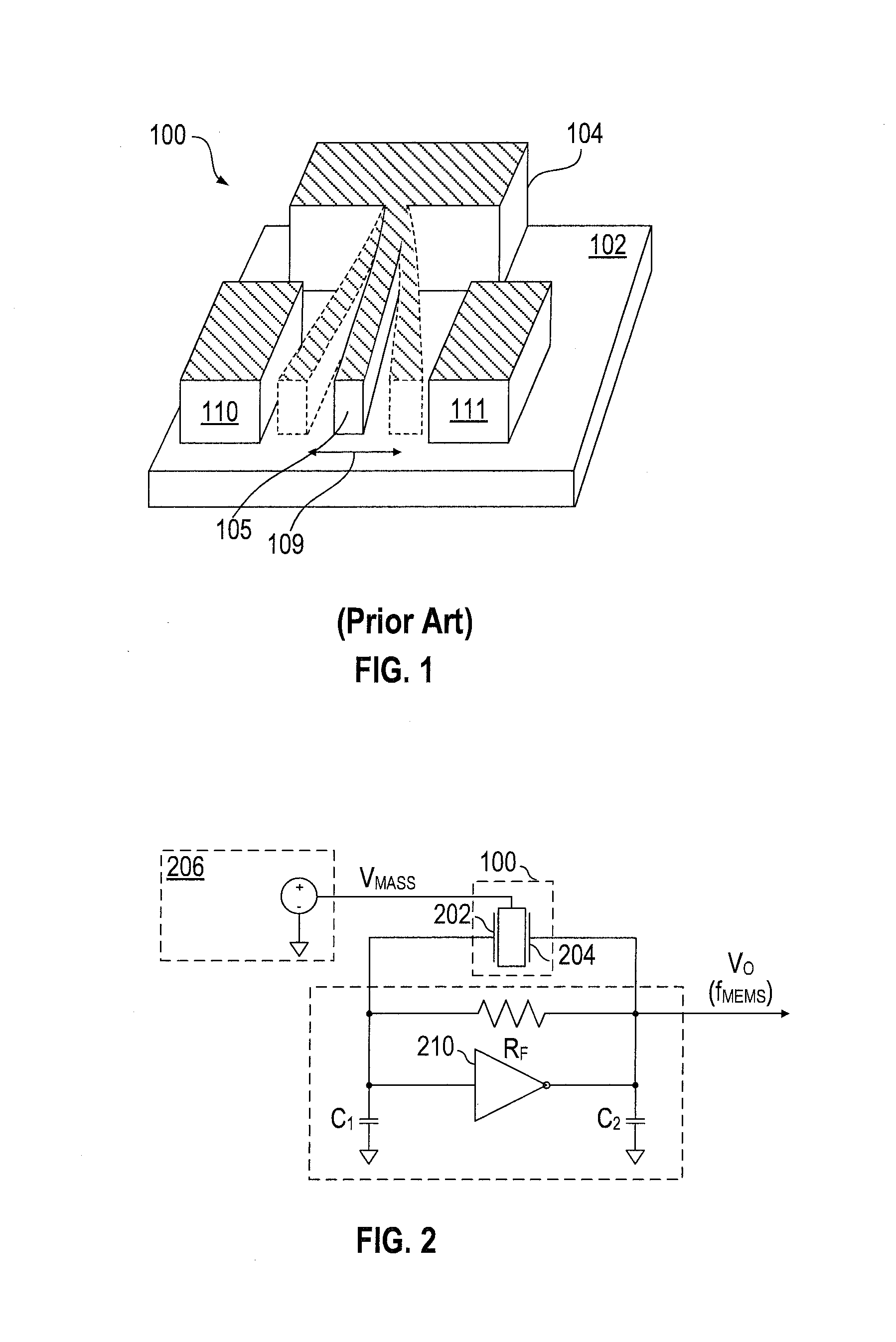
[0035]Referring back to FIG. 1, MEMS device 100 may be modeled as a spring-mass system having a resonant frequency,

f0=12πkm,

where k is a constant indicative of the spring stiffness, m is mass of the resonator, and f0 is the resonant frequency. In general, the quality factor, Q, characterizes a resonator's bandwidth relative to its center frequency. The quality factor may be represented as Q=2πfom / γ, where γ is damping coefficient (e.g., due to fluid in a cavity surrounding the mass). A higher Q indicates a lower rate of energy loss relative to the stored energy of the resonator, i.e., oscillations die out more slowly. An oscillator with a higher Q resonates with higher amplitude but for a smaller range of frequencies around that frequency over smaller bandwidth. To achieve a high-precision, low-power resonator, a high mass may be desired so that the device can have a high stiffness. Increasing mass m increases the quality factor of the resonator if the other relevant parameters for ...


PUM

PropertyMeasurementUnit
Young's modulus temperature coefficientaaaaaaaaaa

Abstract

A technique decouples a MEMS device from sources of strain by forming a MEMS structure with suspended electrodes that are mechanically anchored in a manner that reduces or eliminates transfer of strain from the substrate into the structure, or transfers strain to electrodes and body so that a transducer is strain-tolerant. The technique includes using an electrically insulating material embedded in a conductive structural material for mechanical coupling and electrical isolation. An apparatus includes a MEMS device including a first electrode and a second electrode, and a body suspended from a substrate of the MEMS device. The body and the first electrode form a first electrostatic transducer. The body and the second electrode form a second electrostatic transducer. The apparatus includes a suspended passive element mechanically coupled to the body and electrically isolated from the body.

Description

CROSS REFERENCE TO RELATED APPLICATIONS[0001]This application claims benefit under 35 U.S.C. §119 of provisional application No. 61 / 831,324, entitled “Monolithic Body MEMS Devices,” filed Jun. 5, 2013, which application is hereby incorporated by reference.BACKGROUND[0002]1. Field of the Invention[0003]The invention is related to microelectromechanical systems (MEMS).[0004]2. Description of the Related Art[0005]In general, microelectromechanical systems (MEMS) are very small mechanical devices. Typical MEMS devices include sensors and actuators, which may be used in various applications, e.g., resonators (e.g., oscillators), temperature sensors, pressure sensors, or inertial sensors (e.g., accelerometers or angular rate sensors). The mechanical device is typically capable of some form of mechanical motion and is formed at the micro-scale using fabrication techniques similar to those utilized in the microelectronic industry, such as using lithography, deposition, and etching processes...

Claims


Application Information

Patent Timeline
Patent Type & Authority Applications(United States)
IPC IPC(8): H03B5/30H03L1/02
CPCH03L1/02H03B5/30H03H3/013H03H9/02259H03H2009/02291H03H2009/0248H03H2009/2442H03H2009/02385B81B3/0081H03L1/04Y10T29/49117Y10T29/49005H02N1/00H03H2007/006
Inventor QUEVY, EMMANUEL P.KOURY, JR., DANIEL N.
Owner SILICON LAB INC
Why Eureka
Try Eureka