Pointing device and method

Active Publication Date: 2009-07-02
MICROSOFT TECH LICENSING LLC
View PDF23 Cites 134 Cited by
  • Summary
  • Abstract
  • Description
  • Claims
  • Application Information

AI Technical Summary

Benefits of technology

[0010]In an additional embodiment of the present invention a reflective area and/or a light source, used to indicate activation of the tr

Problems solved by technology

Furthermore, use of methods such as stereoscopic gesture recognition is inherently inferior to other methods, such as depth measuring methods, for example measurement of time-of-flight (TOF) of a light pulse by a depth measuring arrangement an

Method used


Image

  • Pointing device and method
  • Pointing device and method
  • Pointing device and method

Examples


Embodiment Construction

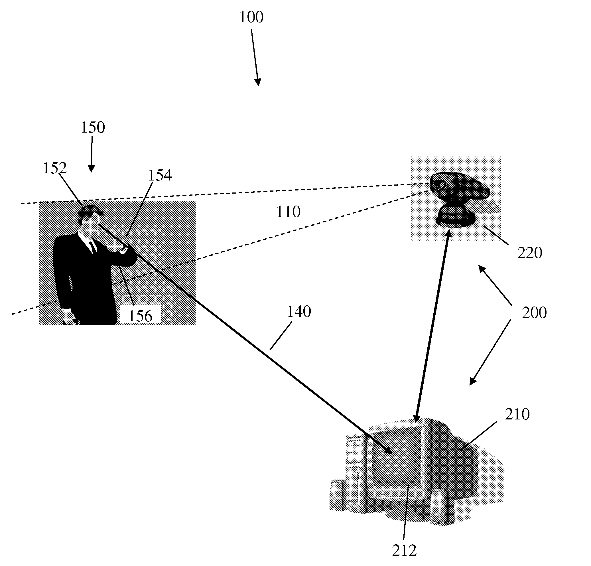
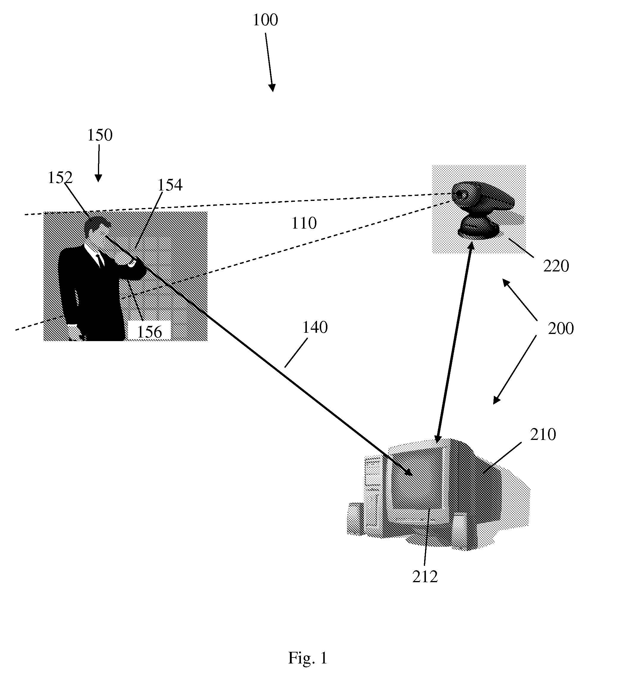
[0016]In the method based on the Time-Of-Flight (TOF) principle, the depth information may be captured and acquired by emitting pulses of radiation to all objects in the scene and sensing the reflected light from the surface of each object. Depth information for each pixel may be transmitted using an additional channel (which called in some instances ‘D’ channel). The information representing the depth of a pixel may be interpreted in a suitable computing system. All objects in the scene may then be arranged in layers according to the distance information sensed by the depth pixels in the camera, providing the depth information in real time as standard black and white video where the grey-level correlates to relative distance. In this method, color data may be provided, for example, by using a normal color imaging sensor.

[0017]3-D imaging of a body based on TOF is described in several references, including U.S. Pat. No. 6,057,909 for the applicant of the present invention. TOF 3-D i...


PUM


Abstract

A system and method for identifying a pointing organ or a pointing device in a field of imaging of a 3-D imaging system and for calculating a line of pointing relative to this organ or device are disclosed. The method and system may be used to enable a user to communicate with computer programs, such as computer games, 3-D design programs and the like. The method and system may further employ a trigger-like mechanism to identify a movement of a user that may be interpreted as trigger activation.

Description

BACKGROUND OF THE INVENTION[0001]Depth measurement in video scenery in general and Gesture Recognition are topic in computer science with goal of interpreting gestures of human or other bodies via specialized equipment and mathematical algorithms. Gestures may originate, for example, from any bodily motion or state. Some systems use two video stereo cameras together with a positioning reference such as a set of infrared emitters to enable automated recognition of the contour of a body in the field of view of the cameras and to identify certain movements of organs or portions of the body so that the identified movements or gestures may be used for communicating of the human with application running in communication with the gesture recognition system. Some of the systems using stereoscopic gesture identification rely on a process which pairs features of a first stereo video image with features of a second stereo video image.[0002]Other systems may employ depth measurement of points o...

Claims


Application Information

Patent Timeline
IPC IPC(8): G06F3/033
CPCG06F3/0304G06F3/011G06F3/013
Inventor KLIER, ZVIKATZ, SAGIMARDER, MATTIASYAHAV, GIORA
Owner MICROSOFT TECH LICENSING LLC
Why Eureka
Try Eureka