Optical Touch Panel

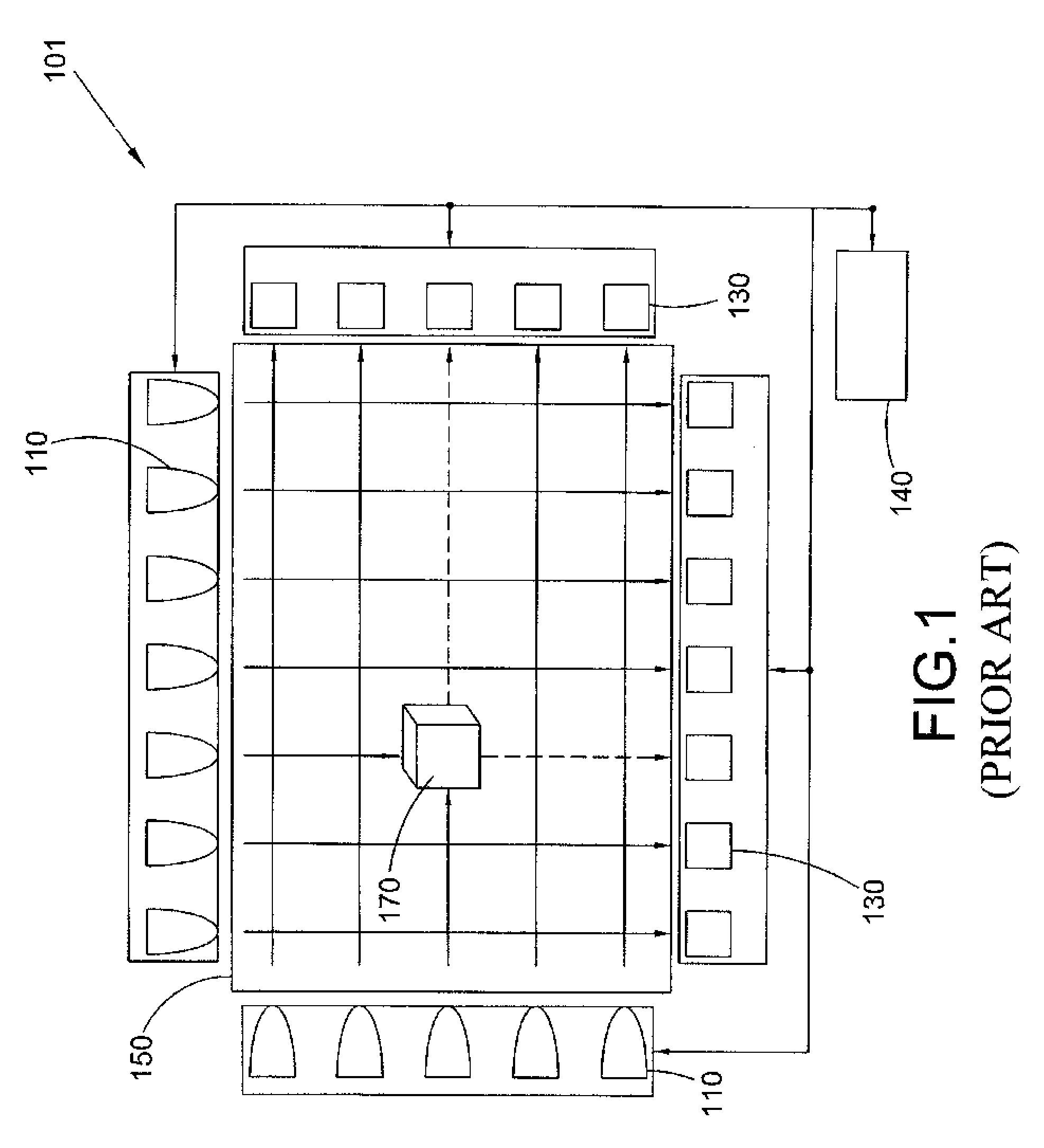
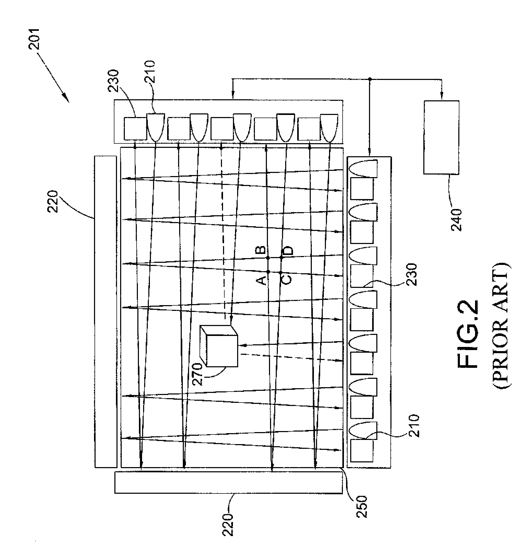
a touch panel and optical technology, applied in the field of optical touch panel improvement, can solve the problems of difficult assembly, complicated optical touch panel b>101/b>, difficult to reduce its size, etc., and achieve the effect of increasing resolution

Inactive Publication Date: 2009-07-02
IBM CORP
View PDF10 Cites 43 Cited by
  • Summary
  • Abstract
  • Description
  • Claims
  • Application Information

AI Technical Summary

Benefits of technology

[0015]The various embodiments described herein provide an optical touch panel having a construction which may have increased resolution (i.e., accuracy). Light-emitting elements may be arranged along one side of a position-detecting surface in a lengthwise direction, while light-receiving elements may be arranged along another side positioned opposite to the light-emitting elements in the lengthwise direction. Thus, sunlight will not affect detection of the position of an object positioned on the position-detecting surface. Accordingly, the light gate design for each light-receiving element may be saved.

Problems solved by technology

Thus, the optical touch panel 101 is complicated, its assembly difficult, and it is difficult to reduce its size.

Method used


Image

  • Optical Touch Panel
  • Optical Touch Panel
  • Optical Touch Panel

Examples


Embodiment Construction

[0034]The following describes various exemplary embodiments. The disclosed embodiments are only for illustration. Thus, it will be understood by those skilled in the art that there are many modifications that may be made to the various embodiments described herein without departing from the spirit and scope of the disclosure. Throughout the drawings, similar features are identified by similar reference numerals.

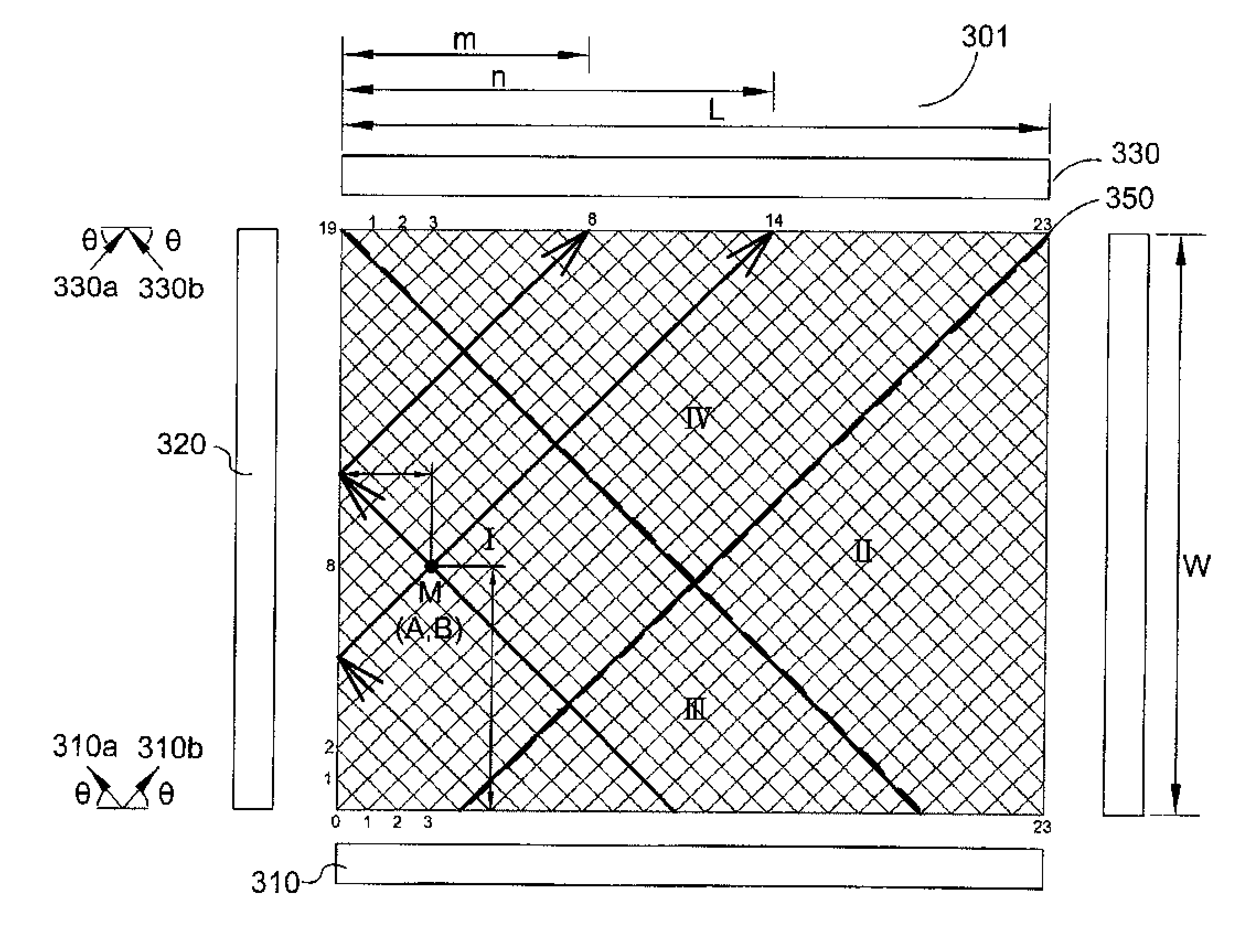
[0035]With reference to FIG. 3, a schematic diagram of the construction of an optical touch panel 301 is provided. The optical touch panel 301 may comprise a rectangular position-detecting surface 350 with a specified length L and a specified width W (wherein L may be greater than or equal to W), a plurality of light-emitting element pairs (310a, 310b), two reflectors (e.g., mirrors) 320, and a plurality of light-receiving element pairs (330a, 330b). Each light-receiving element may be configured for receiving light beams reflected by the reflectors 320 or light beams directl...


PUM


Abstract

An optical touch panel is provided, which may comprise a rectangular position-detecting surface; a plurality of light-emitting element pairs configured for emitting a plurality of light beams; two reflectors configured for reflecting the plurality of light beams emitted by the plurality of light-emitting element pairs; and a plurality of light-receiving element pairs configured for receiving the plurality of light beams emitted by the plurality of light-emitting element pairs. The optical touch panel further may comprise a control circuit configured for causing the light-emitting element pairs to emit the plurality of light beams in a predetermined order to scan the position-detecting surface, and further configured for causing the plurality of light-receiving element pairs to receive the plurality of light beams, thereby forming optical paths on the position-detecting surface in a grid pattern. The control circuit further may be configured for determining the coordinates of an object positioned on the position-detecting surface.

Description

RELATED APPLICATION[0001]This application claims priority under 35 U.S.C. § 119 to Taiwanese Patent Application No. 96151662 filed Dec. 28, 2007, the entire text of which is specifically incorporated by reference herein.FIELD OF THE INVENTION[0002]The various embodiments described herein relate to an improved optical touch panel, and, more particularly, to an infrared (IR) touch panel.BACKGROUND OF THE INVENTION[0003]A variety of touch panel technologies are presently in existence, including resistive technology, capacitive technology, surface acoustical wave (SAW) technology, infrared (IR) technology, etc.[0004]In the case of IR touch panel technology, infrared emitter / collector pairs are used to project an invisible grid of light a small distance over the surface of the panel. When a beam is interrupted, the absence of the signal at the collector is detected and converted to touch coordinates (e.g., X / Y rectangular coordinates). Since the method of determining a touch is optical i...

Claims


Application Information

Patent Timeline
Patent Type & Authority Applications(United States)
IPC IPC(8): G06F3/042
CPCG06F3/0421
Inventor XUAN, HAWAII WYLEE, EDWARD YSCHEN, KENJI CCPARSONS, ROBERT D.
Owner IBM CORP
Why Eureka
Try Eureka