Method for calibrating coordinates of touch screen

Inactive Publication Date: 2009-07-02
ELAN MICROELECTRONICS CORPORATION
View PDF1 Cites 28 Cited by
  • Summary
  • Abstract
  • Description
  • Claims
  • Application Information

AI Technical Summary

Benefits of technology

[0007]It is therefore an object of the invention to provide a method for calibrating coordinates of a touch screen

Problems solved by technology

After a long period of time, the liquid crystal display may be damaged.
In addition, the resolution of the resistive sensor is lower, and the condition of the unprecise coordinate positioning tends to occ

Method used


Image

  • Method for calibrating coordinates of touch screen
  • Method for calibrating coordinates of touch screen
  • Method for calibrating coordinates of touch screen

Examples


Embodiment Construction

[0027]The present invention will be apparent from the following detailed description, which proceeds with reference to the accompanying drawings, wherein the same references relate to the same elements.

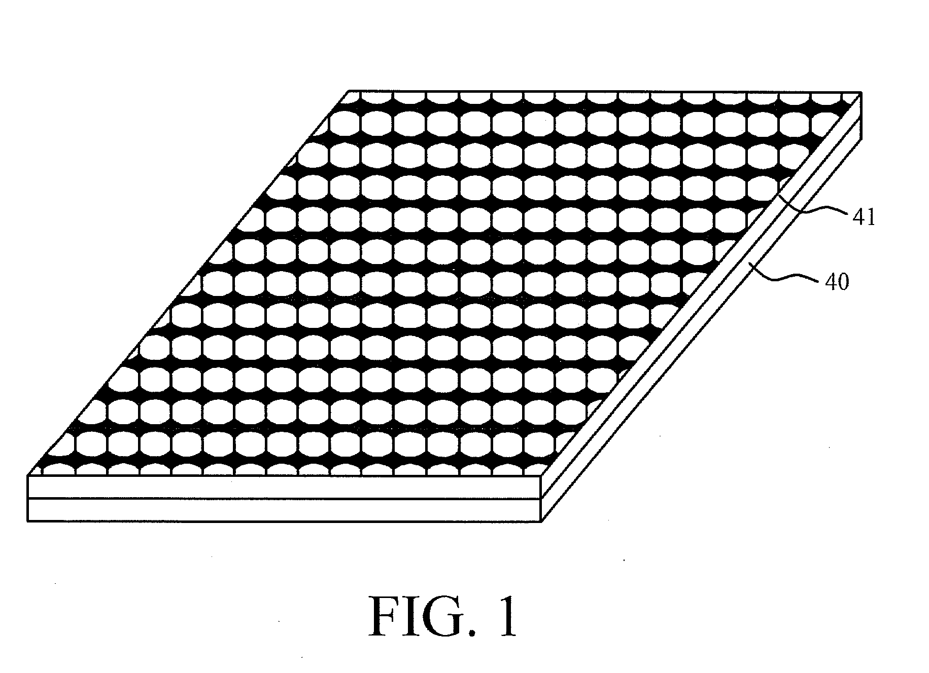
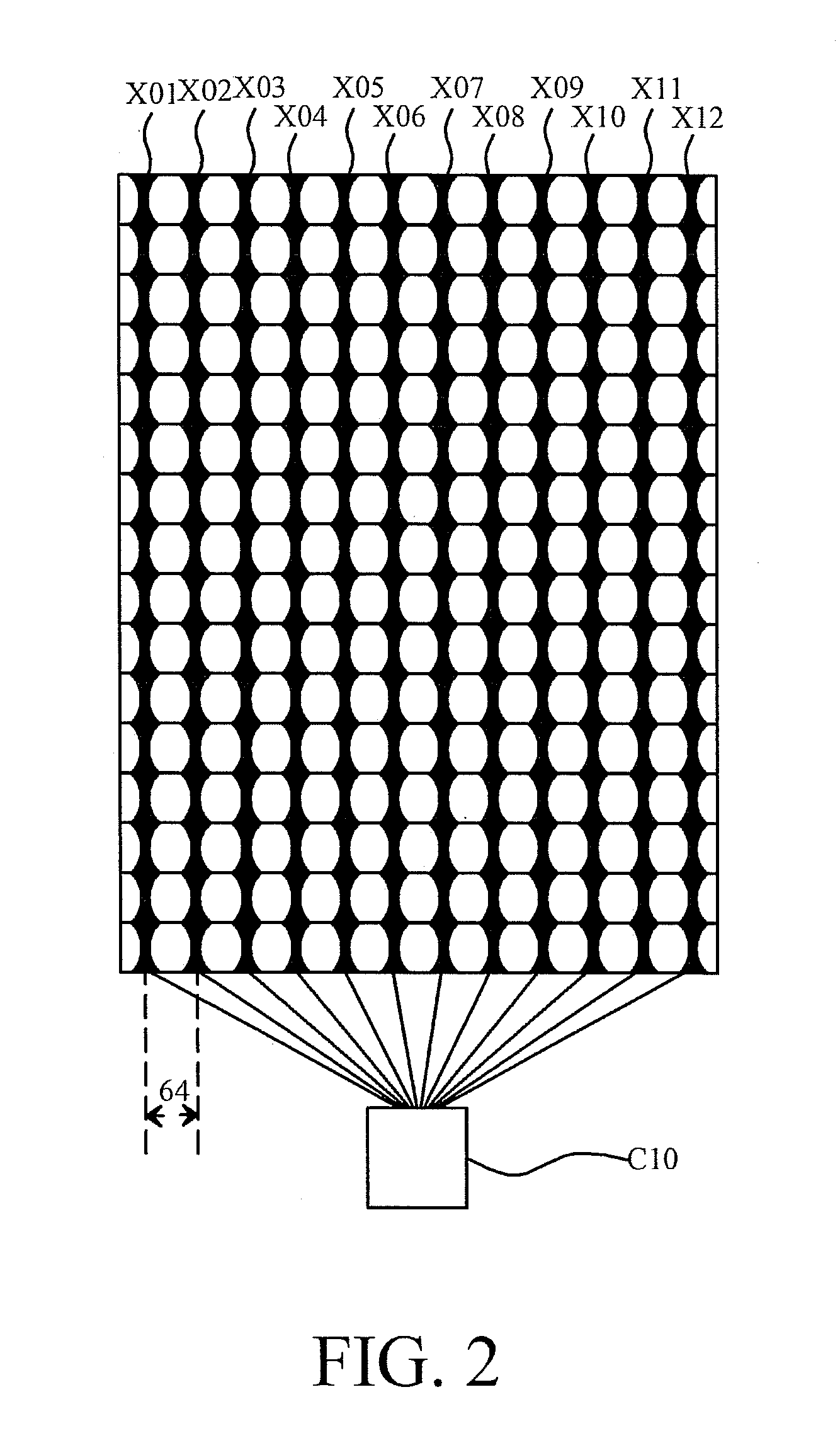
[0028]FIG. 1 is a cross-sectional view showing a structure of a capacitive touch screen according to an embodiment of the invention. Referring to FIG. 1, the capacitive touch screen includes a display module 40 and a capacitive sensor 41. FIG. 2 is a top view showing a structure of the capacitive sensor 41 according to the embodiment of the invention. Referring to FIG. 2, the capacitive sensor 41 includes a plurality of X-axis sensing electrodes X01 to X12 and a control circuit C10. Because the X-axis coordinate and the Y-axis coordinate have to be provided to position an indicator. In this embodiment, only the method for positioning the X-axis coordinate is illustrated, and the method for positioning the Y-axis coordinate may be the same as that for positioning the X-axis coordinate,...


PUM


Abstract

A method for calibrating coordinates of a touch screen includes the steps of: providing a display panel, which includes display coordinates along a first axis and a first axis display coordinate; providing a capacitive sensor, which includes sensing electrodes disposed along the first axis and respectively corresponding to sensing coordinates, wherein capacitive sensor has a maximum sensing coordinate; detecting digital values corresponding to the sensing electrodes when the capacitive sensor is touched; multiplying the digital values by the sensing coordinates corresponding to the sensing electrodes to obtain a weighting value; dividing the weighting value by the maximum sensing coordinate to obtain an interpolated value; and multiplying the interpolated value by the first axis display coordinate to obtain a calibrated coordinate.

Description

[0001]This application claims priority of U.S. Provisional Application No. 61 / 016,754 filed on Dec. 26, 2007 under 35 USC 119, the entire contents of which are hereby incorporated by reference.BACKGROUND OF THE INVENTION[0002]1. Field of Invention[0003]The invention relates in general to the indicator positioning technology, and more particularly to a method for calibrating coordinates of a touch screen.[0004]2. Brief Discussion of the Related Art[0005]Recently, the technology is rapidly developed. A handheld device, such as a smart mobile phone, a personal digital assistant (PDA), a global positioning system (GPS), or the like, has become more and more popularized. The above-mentioned devices have touch screens, so the calibrating technology between a touch sensor and a display device become very important. In the past, a resistive touch sensor is usually used. The resistive sensor has to sense the coordinates of indicators on the screen by way of pressure sensing. A liquid crystal...

Claims


Application Information

Patent Timeline
IPC IPC(8): G06F3/045G06F3/041
CPCG06F3/044G06F3/0418G06F3/04186
Inventor LEE, CHIA-YILEE, WEN-KAI
Owner ELAN MICROELECTRONICS CORPORATION
Why Eureka
Try Eureka