DAC (Digital Analog Converter) calibrating circuit and calibrating method thereof

A technology for calibrating circuits and circuits, which is applied in the field of DAC, can solve the problems of comparator comparison result error, failure to apply, static current can not be well matched, etc., to achieve the effect of solving errors

Active Publication Date: 2011-01-19
ETOWNIP MICROELECTRONICS BEIJING CO LTD
View PDF5 Cites 11 Cited by
  • Summary
  • Abstract
  • Description
  • Claims
  • Application Information

AI Technical Summary

Problems solved by technology

These two design defects will cause a certain error in the comparison result of the comparator, which directly leads to the inability to match the MSB current and the LSB quiescent current well. Therefore, this calibration circuit cannot be applied to a high-precision DAC.

Method used


Image

  • DAC (Digital Analog Converter) calibrating circuit and calibrating method thereof
  • DAC (Digital Analog Converter) calibrating circuit and calibrating method thereof
  • DAC (Digital Analog Converter) calibrating circuit and calibrating method thereof

Examples


Embodiment Construction

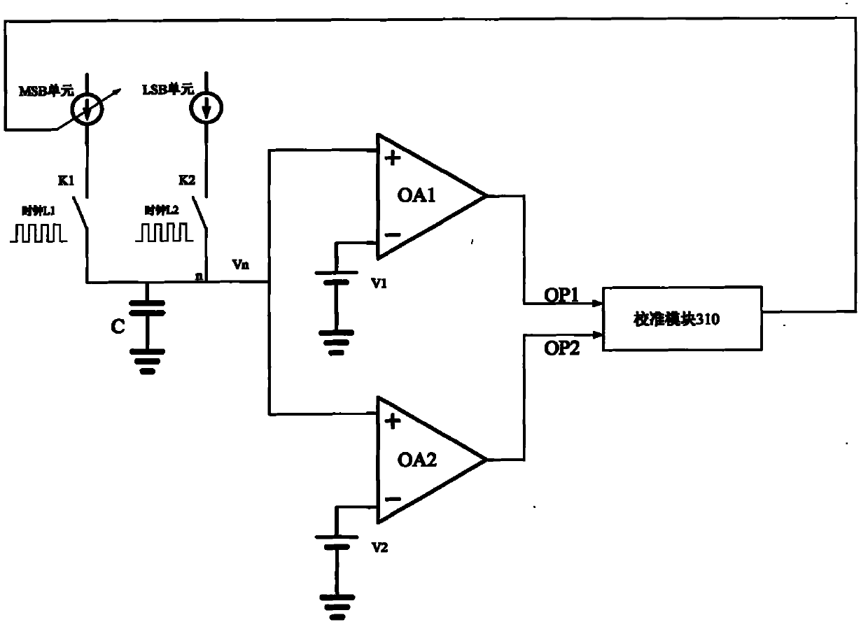
[0030] image 3 It is a structural block diagram of a DAC calibration circuit according to an embodiment of the present invention. The calibration circuit includes an MSB unit, an LSB unit, a switch K1, a switch K2, a clock L1, a clock L2, a capacitor C, a comparator OA1, a comparator OA2, a voltage source V1, A voltage source V2 and a calibration module 310 .

[0031] The MSB unit is connected to the switch K1 to control the conduction state of the MSB unit; the LSB unit is connected to the switch K2 to control the conduction state of the LSB unit; the clock L1 outputs a clock signal to the switch K1 to control the opening and closing of the switch K1; The clock L2 also outputs a clock signal to the switch K2 to control the switch K2 to be turned on and off.

[0032] The switches K1 and K2 are connected to the capacitor C at point n, so as to control the charging and discharging of the capacitor C by the MSB unit or the LSB unit through the ON state of the switches K1 and K2...


PUM


Abstract

The invention relates to a DAC calibrating circuit and a calibrating method thereof. The DAC calibrating circuit comprises a first switch, a second switch, a first comparator, a second comparator, a capacitor and a calibrating module, wherein the first switch is connected between an LSB (Least Significant Bit) unit and the capacitor in order to enable the LSB unit to charge the capacitor based onthe control of a first signal; the second switch is connected between the MSB unit and the capacitor in order to enable the MSB unit to charge the capacitor based on the control of a second signal; the in-phase end of the first comparator is connected with connecting points among the MSB unit, the LSB unit and the capacitor; the reversed-phase end of the first comparator is a first fixed voltage;the in-phase end of the second comparator is connected with the in-phase end of the first comparator, the reversed-phase end of the second comparator is a second fixed voltage; and the calibrating module receives a comparative result of the first comparator and the second comparator and regulates the current of the MSB unit and/or the LSB unit in real time. The invention has high calibration accuracy and can be widely used for high-accuracy DAC.

Description

technical field [0001] The present invention relates to a mixed signal circuit, in particular to a DAC (digital-to-analog converter, digital-to-analog converter). Background technique [0002] The n-bit precision current DAC circuit is usually composed of two parts, one part is composed of MSB (Most Significant Bit, the most significant bit) unit current source 2 a -1 unit array, the other part is composed of LSB (Least Significant Bit, least significant bit) unit current source 2 b -1 cell array that satisfies [0003] n=a+b [0004] I MSB = 2 b · I LSB (1) [0005] I total =(2 a -1) I MSB +(2 b -1) I LSB [0006] Among them, n is the number of digits of precision of the DAC circuit, I MSB is the MSB cell current, I LSB is the LSB cell current, I total is the total current of the DAC circuit. [0007] figure 1 It is a schematic diagram of the current-mode DAC structure, in which the left diagram is a schematic diagram of an MSB...

Claims


Application Information

Patent Timeline
Patent Type & Authority Applications(China)
IPC IPC(8): H03M1/10
Inventor 朱循宇
Owner ETOWNIP MICROELECTRONICS BEIJING CO LTD
Why Eureka
Try Eureka