LNG gasification system based on double-heat-source heat pump

A gasification system and dual heat source technology, applied in heat pumps, refrigeration and liquefaction, lighting and heating equipment, etc., can solve problems such as limitations, utilization of LNG cold energy, high heating costs, etc., and achieve a wide range of applications

Active Publication Date: 2014-01-01
SOUTH CHINA UNIV OF TECH
View PDF7 Cites 11 Cited by
  • Summary
  • Abstract
  • Description
  • Claims
  • Application Information

AI Technical Summary

Problems solved by technology

LNG needs to be heated and gasified through a gasification system before it is supplied to users. At present, commonly used gasification technologies include seawater open rack gasifier (ORV), submerged combustion gasifier (SCV) and intermediate gasifier (IFV), the above gasification technologies are mature and reliable, but none of them utilize the cold energy of LNG. In addition, ORV and IFV use seawater as a heat source, while SCV needs to burn natural gas for heating. The use of free seawater is limited, and natural gas is used for heating. The application of these mature gasification technologies will be greatly restricted due to the high cost and the trend of utilizing cold energy of LNG
In recent years, countries around the world have proposed LNG cold energy utilization gasification technologies such as cold energy power generation, cold energy air separation, production of liquid carbon dioxide, and construction of freezers. However, the gasification systems designed based on the above gasification technologies often only focus on How to improve the utilization rate of LNG cold energy, while less attention has been paid to the mismatch of cold energy supply and demand end loads in the actual process, the impact of working conditions on the system, and the convenience of the base load heat source of the gasification system, which greatly limits its practical application. For engineering applications, the development of a more environmentally friendly, flexible, stable and practical gasification system will greatly enhance the application range of LNG

Method used


Image

  • LNG gasification system based on double-heat-source heat pump

Examples


Embodiment 1

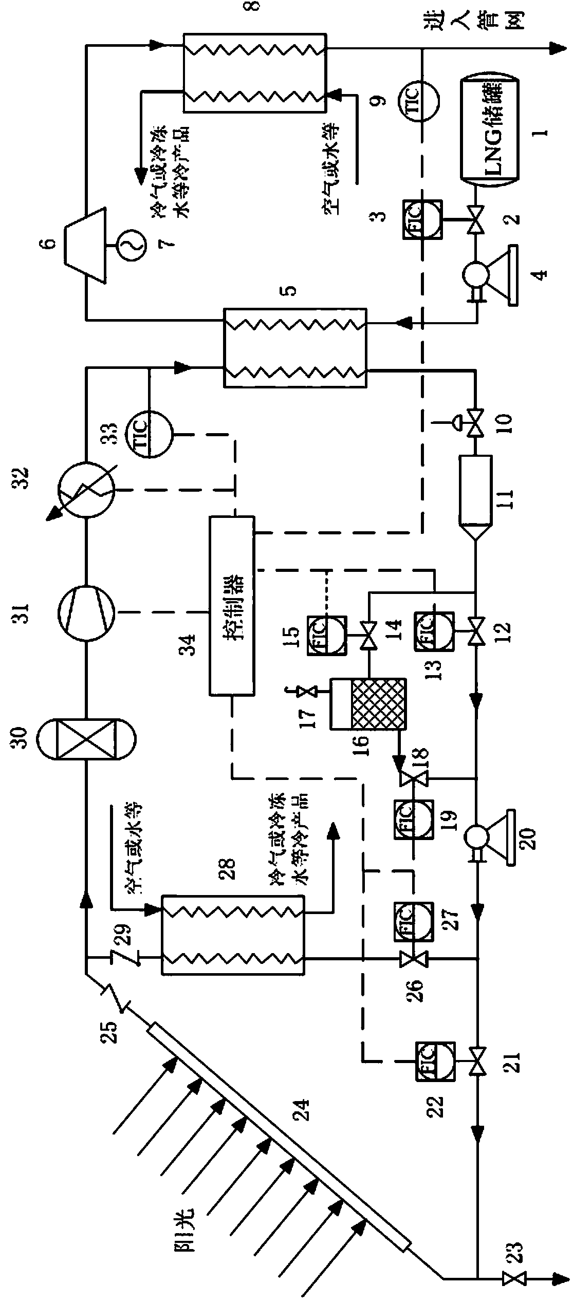
[0031] Such as figure 1 As shown, the LNG gasification system based on the dual heat source heat pump provided by the present invention comprises:

[0032] The LNG gasification heating and expansion main circuit is composed of LNG storage tank 1, electric flow regulating valve 2, LNG booster pump 4, condenser 5, expansion turbine 6 and heat exchanger (8). The main circuit is connected with the natural gas pipe network or user connections;

[0033] An expansion generating unit composed of an expansion turbine 6 and a generator 7;

[0034] Condenser 5, filter 11, cold storage tank 16, working fluid circulation pump 20, first evaporator 24, second evaporator 28 are used to store part of the refrigerant inside the system to prevent liquid shock and Gas-liquid separator 30 for diluting compressor oil due to excessive refrigerant, inverter compressor 31, backup heater 32, electronic expansion valve 10, electric flow control valves 12, 14, 18, 21, 26, breather valve 17, industrial ...


PUM


Abstract

The invention discloses an LNG gasification system based on a double-heat-source heat pump. The LNG gasification system comprises an LNG gasification heating expansion main circuit, an expansion electricity generation unit, a double-heat-source heat pump unit and an automatic control unit. According to the LNG gasification system, the double-heat-source heat pump is introduced, solar energy and air energy serve as gasification system base load heat sources to supply needed heat for LNG gasification, and therefore efficient LNG gasification is achieved; LNG cold energy electricity generation is utilized for supplying energy for power utilization equipment like a compressor and a process pump in the system and supplying cold for an optimized cold energy user end outside the system in a cold air or chilled water or other modes, and therefore reasonable recycle of the LNG cold energy can be achieved flexibly; according to hourly gas requirements and hourly cold supply requirements of a typical design day of a natural gas user end and the optimized cold energy user, a cold storage tank, an inverter compressor, a standby heater and various flow regulation components are adopted, and the system can operate stably under different working conditions through multiple adjustments by a control system.

Description

technical field [0001] The invention relates to LNG gasification technology, in particular to an LNG gasification system based on a dual heat source heat pump. Background technique [0002] With the country's increasing requirements for energy conservation and emission reduction, my country's energy consumption structure will rely more on natural gas. In the next 10 to 20 years, LNG will become the main force in China's natural gas market. LNG needs to be heated and gasified through a gasification system before it is supplied to users. At present, commonly used gasification technologies include seawater open rack gasifier (ORV), submerged combustion gasifier (SCV) and intermediate gasifier (IFV), the above gasification technologies are mature and reliable, but none of them utilize the cold energy of LNG. In addition, ORV and IFV use seawater as a heat source, while SCV needs to burn natural gas for heating. The use of free seawater is limited, and natural gas is used for hea...

Claims


Application Information

Patent Timeline
Patent Type & Authority Applications(China)
IPC IPC(8): F17C7/04F25B30/06
Inventor 樊栓狮孙超郎雪梅王燕鸿温永刚
Owner SOUTH CHINA UNIV OF TECH
Why Eureka
Try Eureka