Vehicle cooling system, control device and control method thereof and engineering machinery

A heat dissipation system and engineering machinery technology, applied in the direction of the power unit, the arrangement of the cooling combination of the power unit, vehicle components, etc., can solve the problems of high cost, low heat dissipation efficiency, and large space occupation, and achieve low cost and improve heat dissipation efficiency , the effect of occupying a small space

Active Publication Date: 2013-02-20
SANY HEAVY IND CO LTD (CN)
View PDF9 Cites 15 Cited by
  • Summary
  • Abstract
  • Description
  • Claims
  • Application Information

AI Technical Summary

Problems solved by technology

[0006] In view of this, the present invention aims to propose a vehicle heat dissipation system, its control device and control method, and construction machi

Method used


Image

  • Vehicle cooling system, control device and control method thereof and engineering machinery
  • Vehicle cooling system, control device and control method thereof and engineering machinery
  • Vehicle cooling system, control device and control method thereof and engineering machinery

Examples


Embodiment Construction

[0039] It should be pointed out that the description and sequence of specific structures in this section are only descriptions of specific embodiments, and should not be considered as limiting the protection scope of the present invention. In addition, the embodiments in this section and the features in the embodiments can be combined with each other under the condition of no conflict.

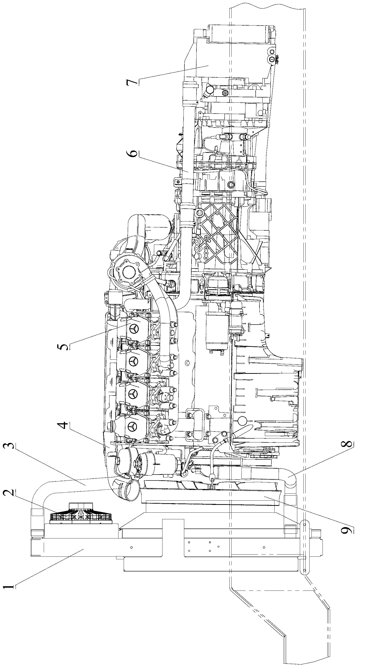
[0040] Please refer to figure 1 , the vehicle cooling system in this embodiment mainly includes a radiator 1, a first fan 2, a second fan 9, an engine cooling pipeline 4, a hydraulic retarder cooling pipeline 6, and the like.

[0041] Wherein, the radiator 1 is installed directly in front of the engine 5, that is, installed on the side of the engine 5 facing the traveling direction (the left side shown in the figure), and the radiator 1 is provided with a first cooling zone and a second cooling zone, As shown in the figure, the first heat dissipation area and the second heat dissipation area ...


PUM


Abstract

The invention relates to the field of engineering machinery, and discloses a vehicle cooling system, a control device and a control method of the vehicle cooling system, and engineering machinery. The vehicle cooling system comprises a heat radiator, a first fan, a second fan, an engine cooling pipeline and a hydrodynamic retarder cooling pipeline, wherein the first fan is arranged in a first cooling area of the heat radiator; the second fan is arranged in a second cooling area of the heat radiator; the engine cooling pipeline is connected with the hydrodynamic retarder cooling pipe to form a cooling loop; and the cooling loop is provided with a cooling liquid outlet and a cooling liquid inlet which are respectively communicated with the outlet end and the inlet end of the heat radiator. Compared with the prior art, the cooling effect of the vehicle cooling system can meet cooling requirements under different situations, so that the cooling ability of the system can be guaranteed, the cooling efficiency of the system is improved, and unnecessary energy waste is avoided; in addition, the vehicle cooling system is low in cost and occupies a small space.

Description

technical field [0001] The invention relates to the field of engineering machinery, in particular to a heat dissipation system for a vehicle, a control device and a control method thereof, and an engineering machinery. Background technique [0002] Hydraulic retarder is also called hydraulic deceleration device. Cars use exhaust brake when going down a long slope. Although they can receive a good braking effect, for construction machinery such as cranes with a large tonnage, the effect of using exhaust brake is relatively limited. Therefore, in order to improve braking performance and ensure driving safety, hydraulic retarders are generally installed on large-tonnage construction machinery. [0003] The original cooling system for getting off the car mainly ensures the cooling effect of the engine, but after the hydraulic retarder is installed, because the hydraulic retarder generates a lot of heat during the working process, in order to ensure the normal operation of the h...

Claims


Application Information

Patent Timeline
IPC IPC(8): B60K11/04B60K11/06
Inventor 何先卫张先腾刘兴龙
Owner SANY HEAVY IND CO LTD (CN)
Why Eureka
Try Eureka