Reactor

a technology of reactors and cylinders, applied in the field of reactors, can solve problems such as failure to assemble stacks, and achieve the effects of reducing the probability of failur

Inactive Publication Date: 2009-07-02
NGK INSULATORS LTD
View PDF4 Cites 5 Cited by
  • Summary
  • Abstract
  • Description
  • Claims
  • Application Information

AI Technical Summary

Benefits of technology

[0030]The present inventors have experimentally confirmed that, in place of employing the “particular separators” having high rigidity, by means of rendering at least one of the upper cover member and the lower cover member higher in rigidity than the plurality of separators, the occurrence of “separation of a joint region” can be reliably restrained even when the stack number is large. That is, the above-mentioned configuration can also effectively restrain the occurrence of “separation of a joint region” caused by “stress concentration caused by increase in stack number,” while restraining the above-mentioned increase in size and cost.

Problems solved by technology

Hereinafter, the separation is referred to as the “separation of a joint region.” Meanwhile, when, in order to restrain the occurrence of the “separation of a joint region,” excess load is applied for joining in assembly of the stack, the sheet body(ies) cracks, resulting in a failure to assemble the stack.

Method used


Image

  • Reactor
  • Reactor
  • Reactor

Examples


Embodiment Construction

[0043]A solid oxide fuel cell (reactor) according to an embodiment of the present invention will next be described with reference to the drawings.

Overall Structure of Fuel Cell:

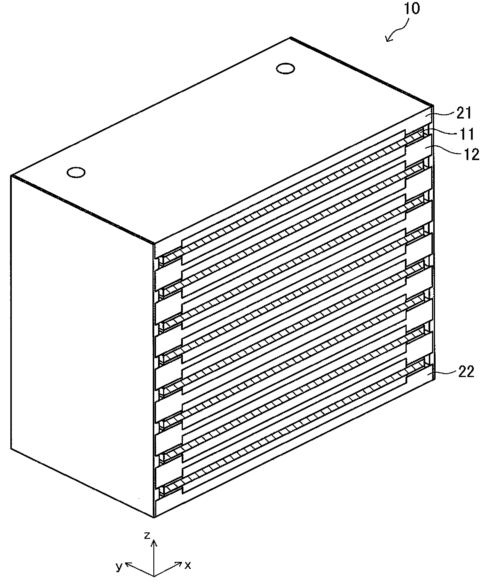
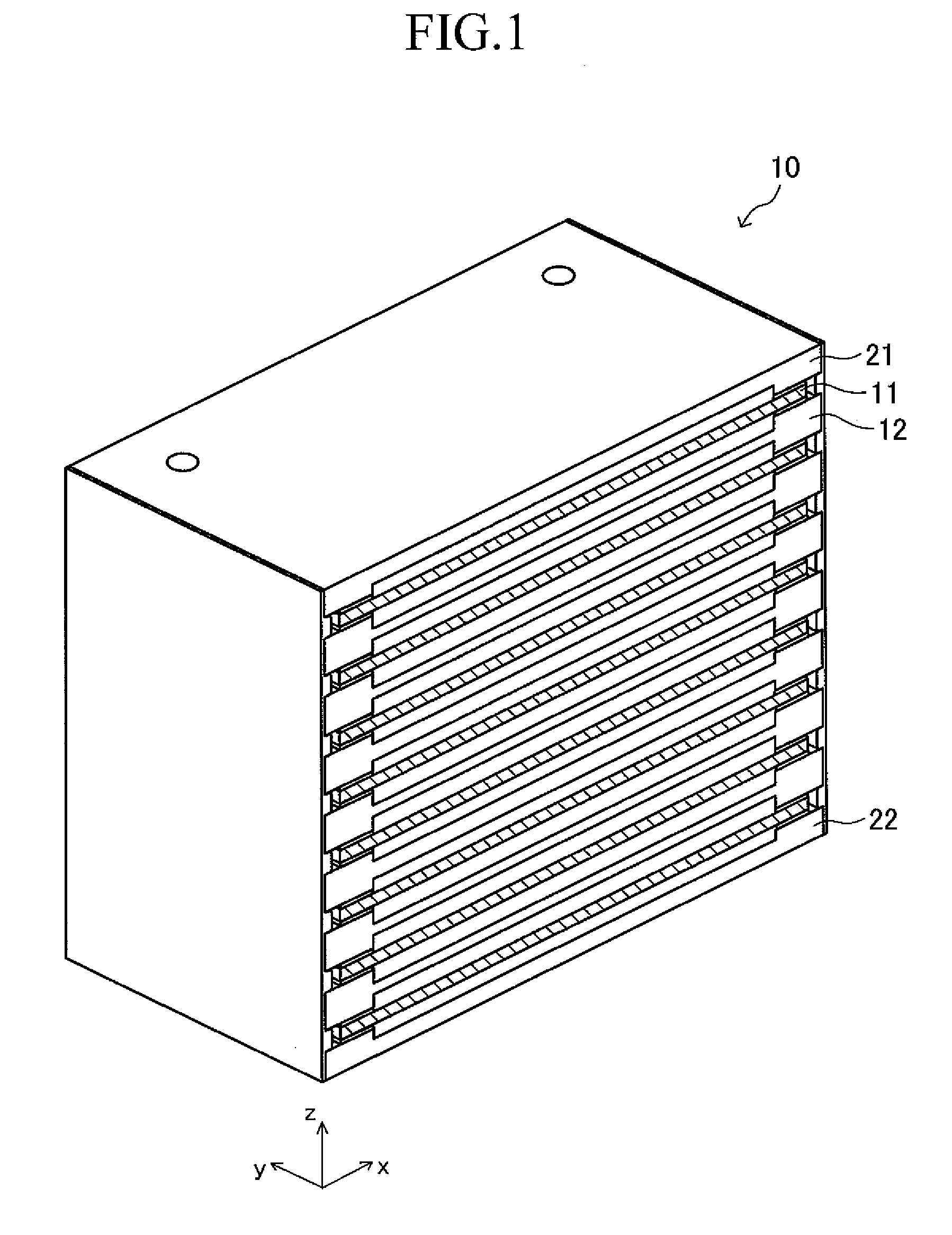
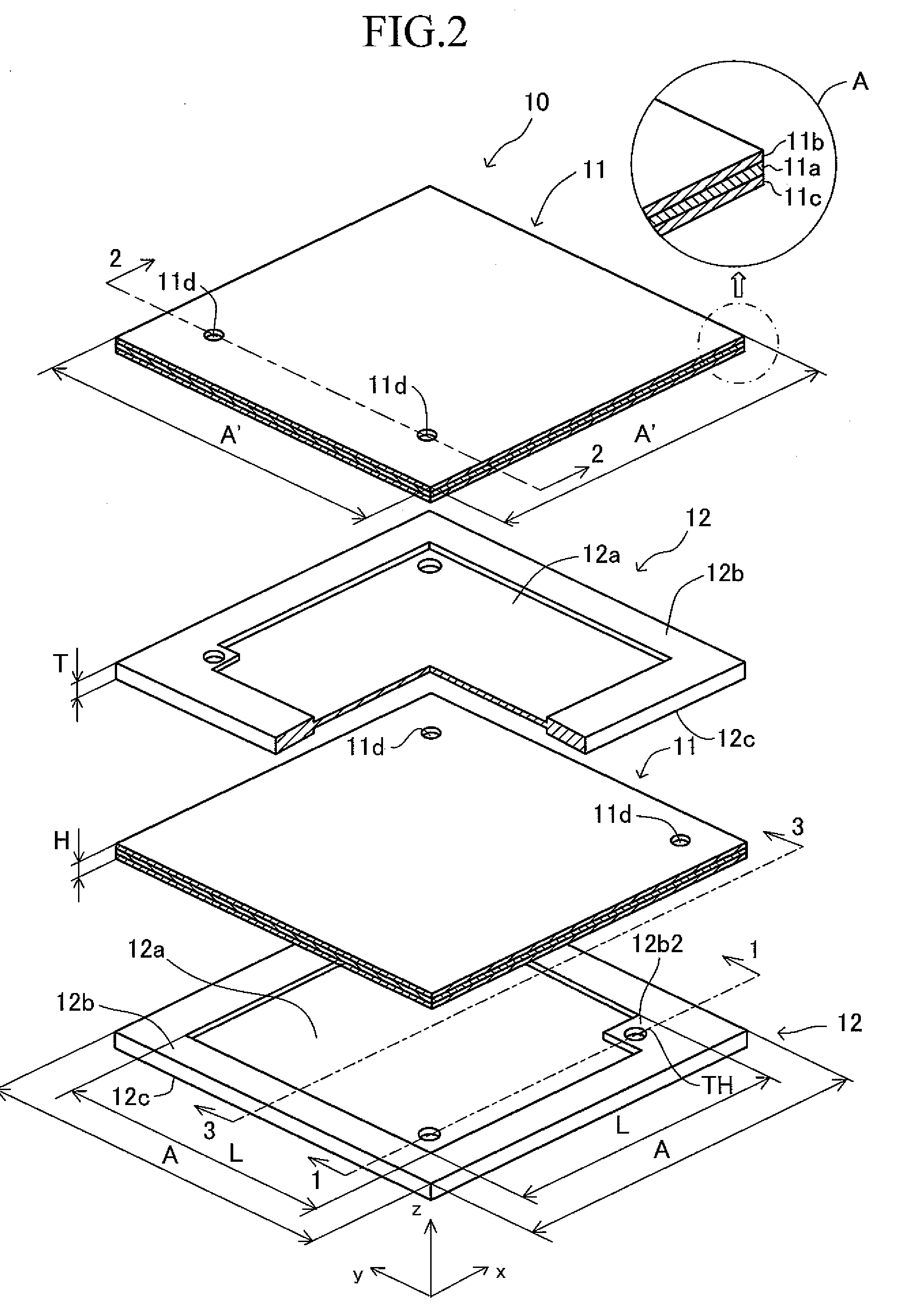
[0044]FIG. 1 perspectively shows, in a cutaway fashion, a solid oxide fuel cell (hereinafter, referred to merely as the “fuel cell”) 10, which is a device according to an embodiment of the present invention. FIG. 2 perspectively and partially shows, in an exploded fashion, the fuel cell 10. The fuel cell 10 is configured such that sheet bodies 11 and separators 12 are stacked in alternating layers. That is, the fuel cell 10 has a flat-plate stack structure.

[0045]In the flat-plate stack structure, an upper cover member 21 fixedly overlies the top sheet body 11, and a lower cover member 22 fixedly underlies the bottom sheet body 11. The sheet body 11 is also referred to as a “single cell” of the fuel cell 10.

[0046]As shown on an enlarged scale within a circle A of FIG. 2, the sheet body 11 is a fired body which...


PUM

PropertyMeasurementUnit
thicknessaaaaaaaaaa
temperatureaaaaaaaaaa
softening pointaaaaaaaaaa

Abstract

A fuel cell employs a stack structure in which a plurality of sheet bodies and a plurality of separators are stacked and joined together in alternating layers. Chemical reactions occur in the sheet bodies. The separators separate, from each other, two kinds of gasses (air and fuel gas) which are necessary for the chemical reactions. The plurality of separators consist of high-rigidity separator(s), and ordinary separators, which are lower in rigidity than the high-rigidity separator. This configuration reliably suppresses the occurrence of “separation of a joint region” attributable to “stress concentration caused by increase in the number of the stacked separators.

Description

BACKGROUND OF THE INVENTION[0001]1. Field of the Invention[0002]The present invention relates to a reactor, such as a solid oxide fuel cell (SOFC), and particularly to a reactor having a (flat-plate) stack structure in which sheet bodies (hereinafter, may be referred to as “single cells”) and separators are stacked in alternating layers.[0003]2. Description of the Related Art[0004]Conventionally, a solid oxide fuel cell having the above-mentioned stack structure has been known (refer to, for example, Japanese Patent Application Laid-Open (kokai) No. 2004-342584). In this case, the sheet body can be a fired body in which a solid electrolyte layer formed from zirconia, a fuel electrode layer, and an air electrode layer are arranged in layers such that the fuel electrode layer is formed on the upper surface of the solid electrolyte layer and such that the air electrode layer is formed on the lower surface of the solid electrolyte layer.[0005]The upper surface of a perimetric portion of...

Claims


Application Information

Patent Timeline
Patent Type & Authority Applications(United States)
IPC IPC(8): H01M8/04H01M8/10H01M2/00
CPCH01M8/0247H01M8/0267H01M8/0273Y02E60/525H01M2008/1293Y02E60/50H01M8/0297H01M8/0258H01M8/2432H01M8/2457H01M8/2483H01M8/2425
Inventor OHMORI, MAKOTOSHIMOGAWA, NATSUMISHINKAI, MASAYUKINANATAKI, TSUTOMU
Owner NGK INSULATORS LTD
Why Eureka
Try Eureka