
Closable Male Luer Connector

a male luer connector and connector technology, applied in the field of male luer connectors, can solve problems such as fear of bacteria generation

Inactive Publication Date: 2009-07-09
KPR U S LLC
View PDF8 Cites 38 Cited by
  • Summary
  • Abstract
  • Description
  • Claims
  • Application Information

AI Technical Summary

Benefits of technology

[0009]In the male luer connector of the present invention having the above characteristic, one end of the body tube inserted into the inner space in the male luer part is moved in the predetermined direction, whereby the male luer part sealing means formed at the one end liquid tightly seal the outlet opening formed at the smaller diameter surface of the male luer part. In this way, since the outlet opening of the male luer part to be the outlet of the liquid is liquid tightly sealed, the outlet opening can be maintained bacteria free while being unused. Further, in the state where the outlet opening is liquid tightly sealed by the male luer sealing means, when one end of the body tube is moved in the opposite direction of the predetermined direction in the inner space of the male luer part, the outlet opening is opened by deviating the male luer sealing means therefrom. Therefore, when the male luer connector is coupled to the male luer connector, the liquid can be flowed to the female luer connector by opening the outlet opening in the course in above.
[0034]The male luer connector in accordance with the invention may further comprise a lock member having a first inner threaded part capable of being helically connected to the female luer connector, said first threaded part being helically engaged with the female luer connector, whereby the male luer part is fixed to the female luer connector while tapered outer peripheral wall is contacted to the inner periphery wall of the female luer connector. By this lock member, the connection of the male luer connector with the female luer connector can be secured to prevent the connection between the male luer connector and the female connector from easily being released by an unexpected external force.

Problems solved by technology

Accordingly, there is a fear of generation of bacteria at the tip end opening of the male luer connector.
Also, there is a fear that the liquid medicine is spilled out of the tip end opening of the male luer connector at priming process and bacteria may be brood at that portion.

Method used


Image

  • Closable Male Luer Connector
  • Closable Male Luer Connector
  • Closable Male Luer Connector

Examples


first embodiment

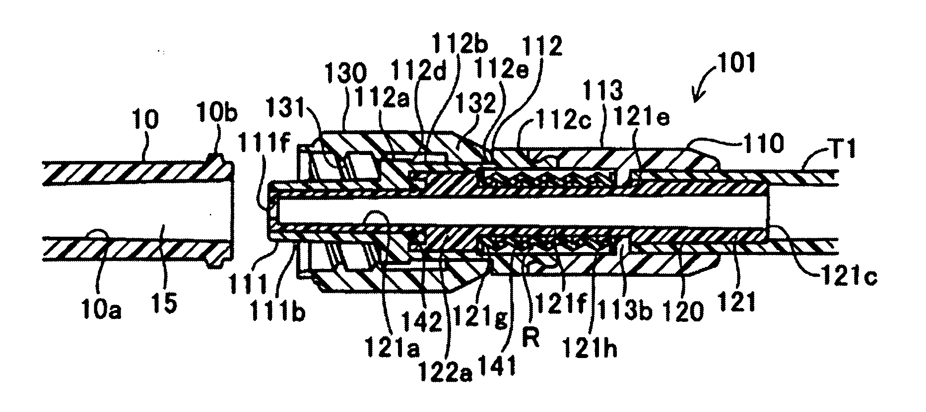
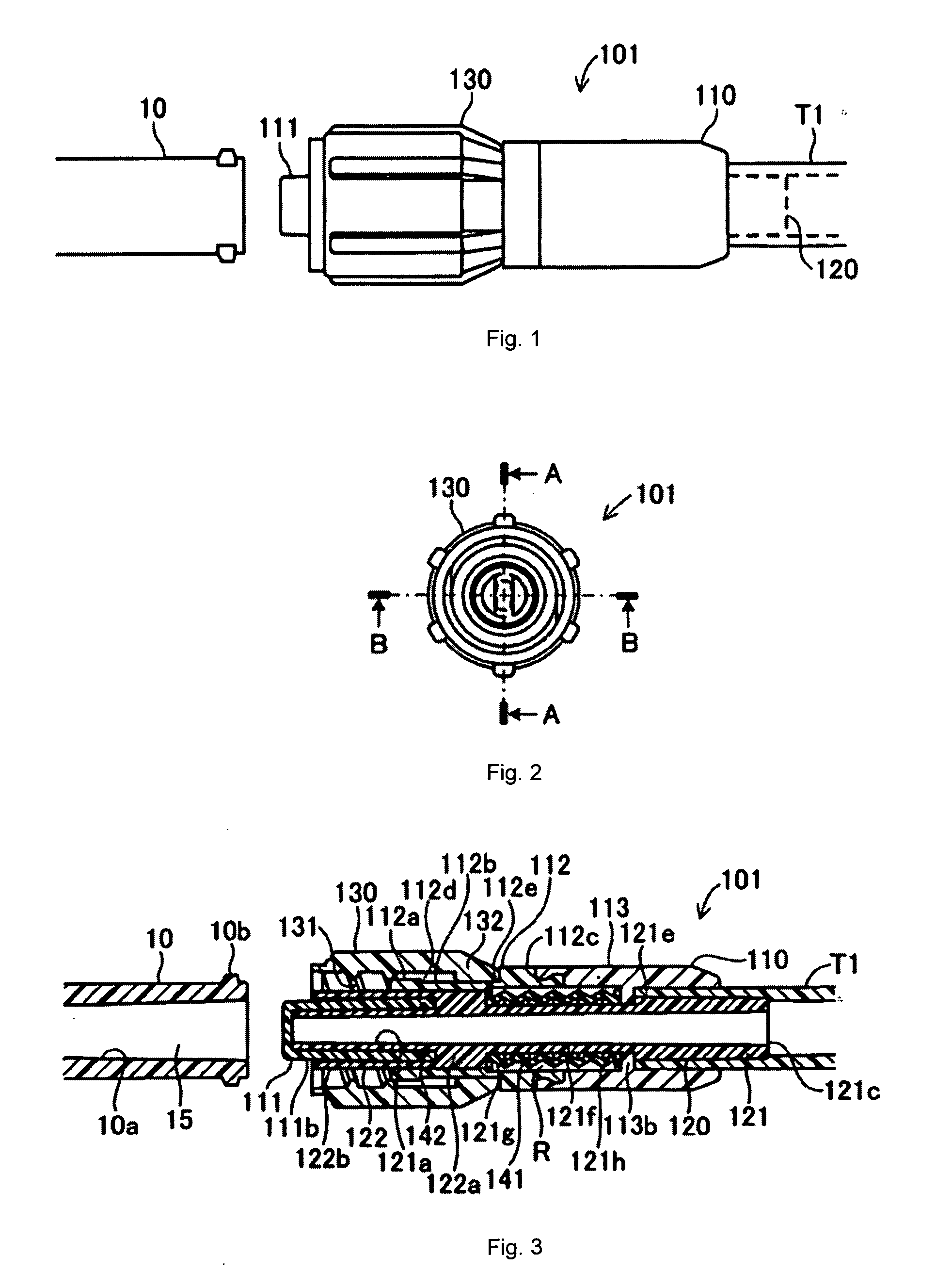
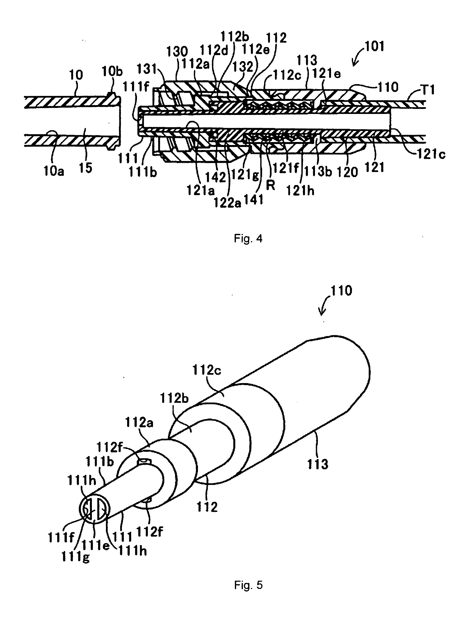
[0060]The male luer connector in accordance with the invention will now be explained in detail with reference to the accompanied drawing in below. FIG. 1 is a plane view of the luer connector of the first embodiment in accordance with the invention; FIG. 2 is a front view, FIG. 3 is a cross sectional view sectioned at A-A in FIG. 2; FIG. 4 is a cross sectional view sectioned at B-B in FIG. 2. As shown in FIG. 1, a male luer connector 101 of the embodiment is connected to a first tube member T1 and coupled to a female luer connector 10 to communicate a flow path space within the first tube member and a flow path within a second tube member (not shown) connected to the female luer connector 10. The male luer connector 101 comprises an outer cylinder part 110, an inner cylinder part 120 and a lock ring 130.

[0061]FIG. 5 is a generally perspective view of the outer cylinder part 110 and FIG. 6 shows only the outer cylinder part 110 of the components illustrated in the cross sectional vie...

second embodiment

[0086]Next, the second embodiment of the invention will be explained. In this embodiment, a filter is provided at the tip end surface of the body tube 121 to allow priming while the outlet opening 111f of the male luer part 111 is liquid tightly sealed by the body tube 121, as well as, the lock ring 130 is helically engaged with the body tube 121 to allow the body tube 121 being moved relative to the male luer part 111 by the rotation of the lock ring 130, which are characteristics in this embodiment. The embodiment will be explained with these characteristics as a main part in below.

[0087]FIG. 17 is a cross sectional view illustrating the male luer connector 102 of the embodiment in accordance with the invention. This cross sectional view is a cross section at A-A in FIG. 2. As shown in this figure, at the tip end surface of the body tube 121 (the left end in the figure), a filter 151 is provided. The filter 151 is a gas permeable filter including a number of fine pores formed ther...

third embodiment

[0096]FIGS. 21 to 24 show the male luer connector 201 of the third embodiment in accordance with the invention. The male luer connector 201 comprises a connector body 210 attached to the tip end of a first tube member T2; a male luer part 220 provided at the tip end of the connector body 210; a moving body tube 230 movably provided within the male luer part 220; a lock ring 240 attached to the outer periphery of the tip end of the connector body 210; and an elastic seal member 250 provided within the center of the connector body 210.

[0097]The connector body 210 comprises a generally cylindrical basal connector 211 in which the diameter is gradually increased from the basal end to be connected to the first tube member T2 to the tip end; a stepped cylindrical tip end support 212 forwardly extended from the tip end of the basal connector 211. The basal connector 211 is formed to have a flow path 211a therein for flowing a liquid medicine and the tip end side of the basal connector 211 ...


PUM


Abstract

The present invention provides a closable male luer connector (101) in which an inner portion (121) within the spigot (111) of the connector is movable from a sealing position to an open position on connection of the connector to a female luer connector (10). The movement of the inner portion may be caused by, for example, action of the female connector on a projecting arm (122b) or a screw thread arrangement.

Description

TECHNICAL FIELD[0001]The invention relates to a male luer connector attachable to a female luer connector having an arrangement for providing a closure when not connected.BACKGROUND OF THE INVENTION[0002]In the medical field, a connector for connecting several kinds of medical tubes is used to form a liquid transfusion, a blood transfusion, dialysis, or a blood collection circuits. The representative connector used in such a case is a commonly normalize luer connector having a tapered shape.[0003]The luer connector is generally formed by a female luer connector and a male luer connector, in which one of medical tubes is connected to the male luer connector and the other medical tube is connected to the female luer connector. Further, by coupling the male luer connector with the female luer connector, the one of the medical tubes and the other medical tube are communicated with each other. In this time, the inner peripheral wall of a tapered shape formed to the female luer connector ...

Claims


Application Information

Patent Timeline
Patent Type & Authority Applications(United States)
IPC IPC(8): A61M39/16
CPCA61M5/165A61M5/385A61M5/38A61M2039/268A61M2205/7536A61M39/26
Inventor KITANI, ICHIROFUNAMURA, SHIGEAKISAKAI, YOSUKEFUJIWARA, NORIFUMI
Owner KPR U S LLC
Learn More