External fixator assembly

a fixator and assembly technology, applied in the field of external fixator assembly, can solve the problems of reducing the versatility and/or accuracy of known devices, affecting the accuracy of fixation, etc., and achieve the effect of reducing or eliminating such known problems

Active Publication Date: 2009-07-09
MDPO LLC
View PDF39 Cites 17 Cited by
  • Summary
  • Abstract
  • Description
  • Claims
  • Application Information

AI Technical Summary

Benefits of technology

[0014]Another feature of the various preferred embodiments of the fixator assembly of the present invention, whether utilizing one or more contoured segments, is the ability to connect one or more transfixion pins or like transfixion members to the one or more contoured segments. When connected to the contoured segment(s) in the intended manner, the transfixion pin(s) or member(s) extends transversely inward, towards the affected portions of the ankle area, from the contoured segment to which it is attached into stabilizing engagement with the bone or other tissue associated with the ankle area at various points along the height or length of the ankle area. Further, each of the one or more transfixion pins can be connected to a contoured segment at a plurality of different locations along the length thereof including, but not limited to, a plurality of locations along the length of the contoured portion of the corresponding contoured segment. The angular and / or convergent configuration of the contoured portion provides significant versatility in positioning each of the one or more transfixion pins or members at any one of a plurality of different locations each representing an orientation having a different height or length relative to the ankle area.
[0015]Therefore, the positioning of the transfixion pin(s) or member(s) into stabilizing engagement with intended tissue of the ankle area, in the manner described herein, eliminates or significantly reduces the need for conventional support blocks or clamps to connect the transfixion pin(s). As set forth above, the use of such known devices and procedures for orienting of the transfixion pins relative to a predetermined body part is time consuming and has a tendency to obscure X-rays or other viewing facilities of the body part. Therefore the use of the various preferred embodiments of the present invention eliminate or significantly reduce such known and well recognized disadvantages.

Problems solved by technology

In utilizing these support blocks, transfixion clamps, etc., one commonly recognized problem or disadvantage associated therewith is the possibility these devices obscuring important or necessary portions of the ankle joint when X-rayed.
In addition, the proper placement of one or more of such clamps, support blocks, etc. is time consuming for medical personnel and may lack a certain versatility and / or accuracy associated with the accurate placement of a transfixion pin or like transfixion member in the fixed orientation or otherwise support of the various bones of the ankle joint.

Method used


Image

  • External fixator assembly
  • External fixator assembly
  • External fixator assembly

Examples


Embodiment Construction

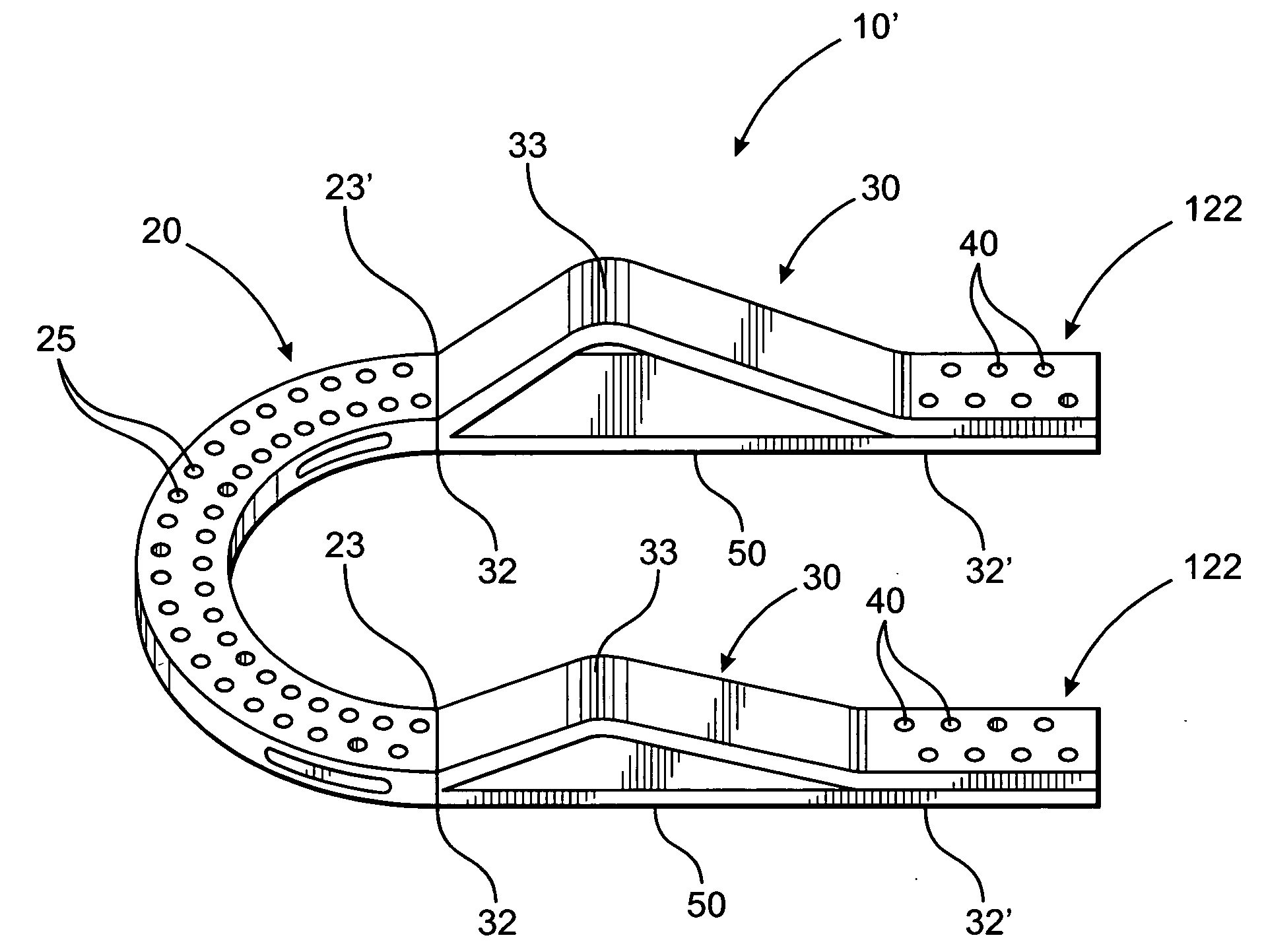
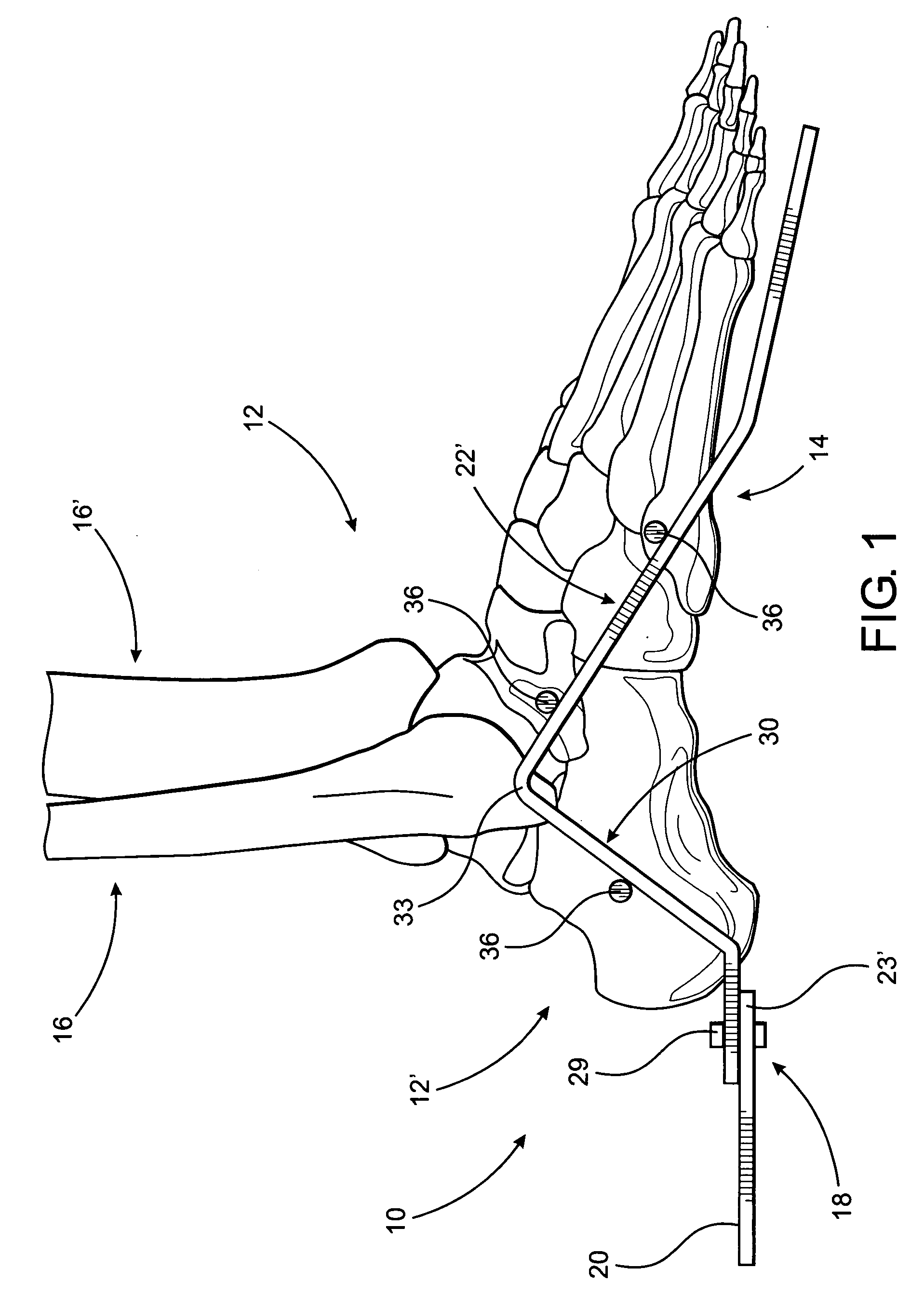
[0031]As represented in the accompanying figures, the present invention is directed to an external fixator assembly generally indicated as 10. As demonstrated, the fixator assembly 10 is structured to be operatively positioned and used in a location substantially adjacent to the ankle area 12 of a patient, as best represented in FIG. 1. As set forth above, the ankle area 12 is meant to be descriptive of substantially the entire area represented in FIG. 1, which includes the ankle joint, foot, corresponding portions of the leg bones, including the fibula and tibia, as well as the associated components and tissue. In addition, the terms “height” and “length” of the ankle area 12 are used synonymously herein and refer to the distance from substantially the bottom of the foot, as at 14, to at least a portion the long bones of the leg, as at 16.

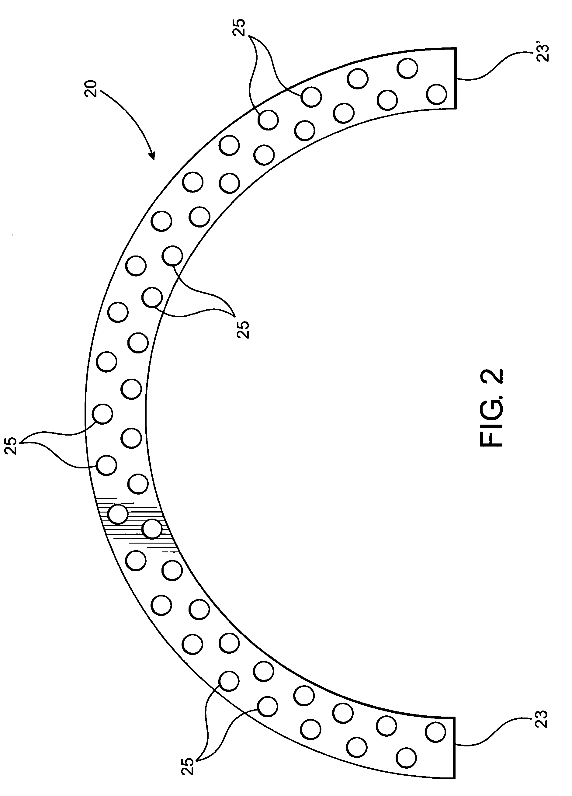
[0032]Accordingly, the external fixator assembly 10 comprises a support assembly generally indicated as 18 and including a base segment 20 and at...


PUM


Abstract

An external fixator assembly structured for placement and use substantially adjacent the ankle area of the body and including a support assembly comprising at least one base segment and one or two contoured segments disposed substantially on opposite sides of the ankle area. Each of the contoured segments includes a contoured portion having a either different or substantially equivalent angular and / or convergent configurations disposed along a length or height of the ankle area. At least one transfixion member may be connected along the length of the contoured portion(s) as well as a remainder of the contoured segment(s) so as to extend transversely inward there from into operative engagement with tissue associated with the ankle area patient's body.

Description

CLAIM OF PRIORITY[0001]The present application is a continuation-in-part application of previously filed, now pending application having Ser. No. 11 / 903,834, filed on Sep. 25, 2007 incorporated herein by reference.BACKGROUND OF THE INVENTION[0002]1. Field of the Invention[0003]This invention is directed to an external fixator assembly structured for operative placement relative to and treatment of the ankle area including the ankle joint, foot and correspondingly disposed lower leg bones. A support assembly comprises a base segment configured to at least partially surround the ankle area and one or more contoured segments each including a contoured portion. The contoured portion extends transversely outward from its contoured segment, along a length or height of the ankle or talus area and is structured to dispose one or more transfixion pins at any of a plurality of preferred orientations to engage and efficiently stabilize predetermined portions of the ankle area.[0004]2. Descript...

Claims


Application Information

Patent Timeline
Patent Type & Authority Applications(United States)
IPC IPC(8): A61B5/00A61F5/01
CPCA61B17/6441A61B17/6425
Inventor MARIN, LUIS E.
Owner MDPO LLC
Why Eureka
Try Eureka